 English
 Español
NEWS
NEWS
NEWS
NEWS
NEWS
NEWS
NEWS
NEWS
NEWS
NEWS
NEWS
NEWS
NEWS
NEWS
NEWS
NEWS

Peng Shulan — Regional Sales Consultant
Home / Author / Peng Shulan — Regional Sales Consultant / Advanced AC/DC/IR Withstand Voltage Testing for Safer Electrical Products
Advanced AC/DC/IR Withstand Voltage Testing for Safer Electrical Products
Content
- 1 The Importance of Withstand Voltage and Insulation Resistance Testing
- 2 Product Overview
- 3 AC Withstand Voltage Testing
- 4 DC Withstand Voltage Testing
- 5 Insulation Resistance Measurement up to 10 GΩ
- 6 Arc Detection for Early Fault Identification
- 7 Eight-Channel Matrix Scanning and Multi-Point Testing
- 8 Programmable Test Parameters
- 9 Memory, Records, and Test Procedure Management
- 10 Operator Interface and Practical Usability
- 11 Interfaces for Laboratory and Automated Production
- 12 Applications in Transformer Testing
- 13 Applications in Motors and Generator Windings
- 14 Applications in Electronic Components and Assemblies
- 15 Advantages over Basic or Single-Function Testers
- 16 Manufacturing Strengths and Engineering Capabilities
- 17 Advanced Manufacturing Process for Electrical Safety Instruments
- 18 Quality Control and Calibration Considerations
- 19 Designing a Safe Test Station
- 20 Using the Instrument in Production
- 21 Engineering and Research Applications
- 22 Environmental and Operating Considerations
- 23 Recommended Selection Approach
- 24 Why the Series Is Suitable for Global Industrial Use
- 25 Best Practices for Reliable Results
- 26 Q&A
- 26.1 What is the main purpose of the TH9201 Series?
- 26.2 What is the maximum AC test voltage?
- 26.3 What is the maximum DC test voltage?
- 26.4 What is the insulation resistance measurement range?
- 26.5 Why is arc detection important?
- 26.6 Does the tester discharge the product after testing?
- 26.7 What is the purpose of the eight-channel matrix scanner?
- 26.8 Can the tester be used on an automated production line?
- 26.9 How many test procedures can be stored?
- 26.10 Which industries can use this instrument?
- 26.11 How should a customer choose between the model configurations?
- 26.12 Is the tester suitable for laboratory and production use?
- 26.13 What safety precautions are necessary?
- 27 Conclusion
- 28 References
- 29 Product: TH9201 Series AC/DC/IR Withstand Voltage Hipot Tester
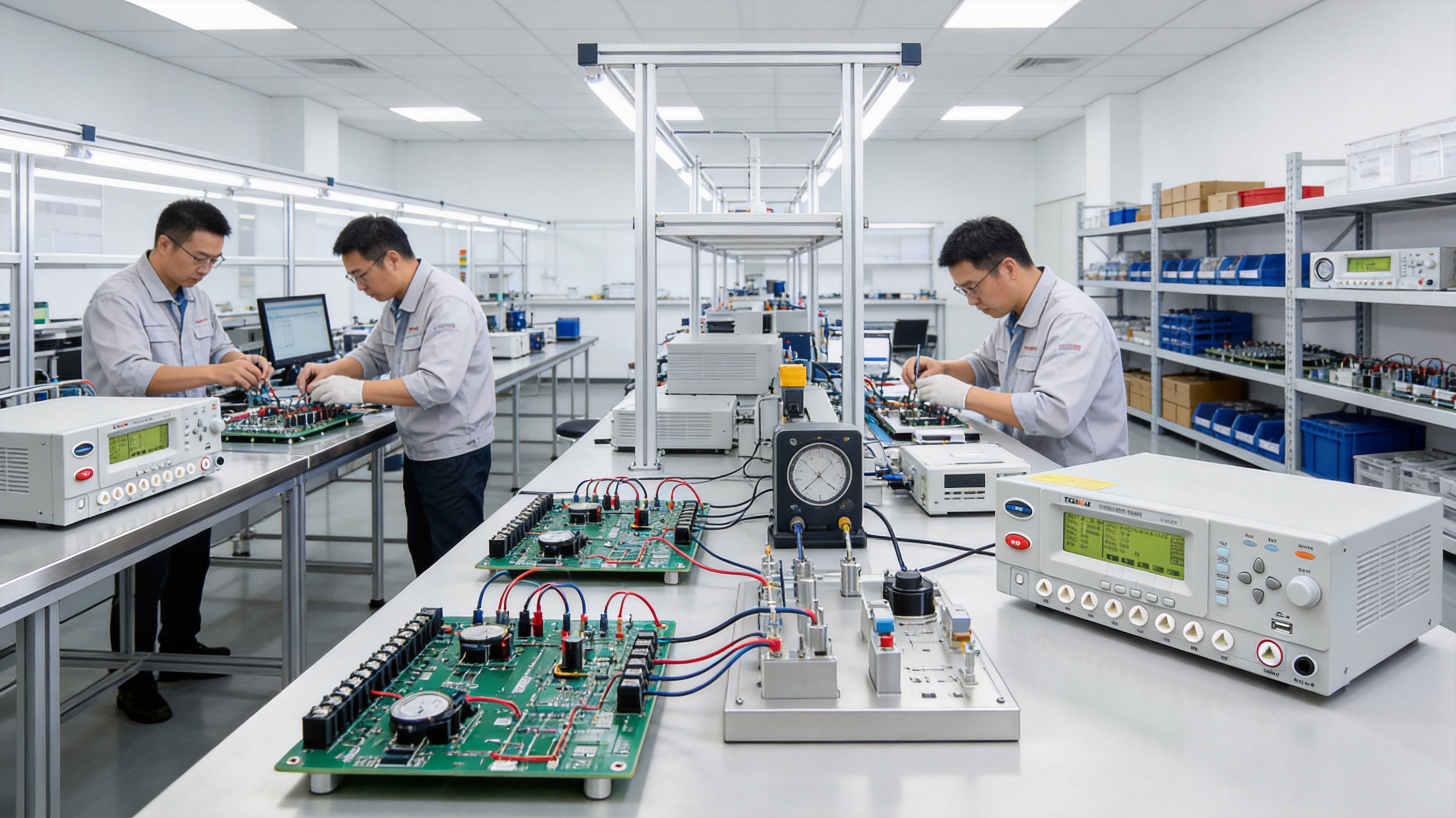
Electrical safety testing is a fundamental requirement in the design, manufacture, inspection, and maintenance of modern electrical and electronic products. Every transformer, motor winding, power supply, capacitor, inductor, harness, insulating material, and assembled electrical product must demonstrate that its insulation system can withstand the electrical stresses expected during operation. A failure in insulation may lead to electric shock, equipment damage, fire, production downtime, or a costly product recall.
The TH9201 Series AC/DC/IR Withstand Voltage Hipot Tester is designed to address these challenges through a combination of high-voltage withstand testing, insulation resistance measurement, arc detection, fast discharge, programmable test sequencing, and automation interfaces. It is a professional electrical safety tester for laboratories, quality-control departments, production lines, repair facilities, and research and development environments.
Unlike a basic single-function hipot instrument, the TH9201 Series brings several important safety tests into one compact platform. Depending on the configuration, users can perform AC withstand voltage testing, DC withstand voltage testing, insulation resistance testing, and arc detection. The instrument also supports adjustable voltage rise time, voltage fall time, waiting time, and test duration, allowing the testing process to be adapted to different products and standards.
Its built-in data storage, 240 × 64 dot matrix LCD, eight-channel matrix scanning capability on applicable models, and standard communication interfaces make the series suitable for both manual operation and automated production. These capabilities help manufacturers improve test consistency while reducing unnecessary handling and setup time.
The Importance of Withstand Voltage and Insulation Resistance Testing
Electrical products are often exposed to voltage levels significantly higher than their normal operating voltage. Short-duration voltage surges may occur because of switching operations, lightning-related transients, motor starting, power-system disturbances, or faults in connected equipment. The insulation system must remain stable under these conditions.
A withstand voltage test, commonly called a hipot test, applies a voltage higher than the product’s normal operating level between conductive parts and accessible metal or between electrically isolated circuits. The purpose is not to simulate normal operation. Instead, it is to reveal weak insulation, insufficient creepage or clearance, contamination, manufacturing defects, damaged winding enamel, assembly errors, and other conditions that could cause breakdown during service.
Insulation resistance testing measures the resistance offered by an insulating material or system when a DC voltage is applied. A low insulation resistance value may indicate moisture, dirt, aging, mechanical damage, incorrect assembly, or a hidden conductive path. Insulation resistance testing is especially valuable for motors, generators, transformers, cables, connectors, power supplies, and electronic assemblies.
Although withstand voltage and insulation resistance tests are related, they provide different information. A product may show acceptable insulation resistance at a relatively low test voltage but still fail when exposed to a higher dielectric stress. Conversely, a product may withstand a high voltage for a short period while showing an insulation resistance value that suggests contamination or gradual degradation. For this reason, many safety-testing programs use both methods.
Arc detection adds another layer of protection and diagnostic capability. An arc may occur when insulation is weak, when a sharp edge concentrates an electric field, or when an air gap becomes electrically conductive. Detecting this event quickly helps prevent continued stress on the product and supports more reliable identification of borderline or defective units.
Product Overview
The TH9201 Series is developed as a professional AC/DC/IR safety testing platform. Its compact streamlined construction allows it to fit comfortably on a laboratory bench or in a production test station. The instrument is designed for efficient operation without sacrificing the control and monitoring functions required for high-voltage testing.
The series is suitable for testing electrical equipment, individual components, assemblies, windings, and insulating materials. Typical applications include transformer safety testing, motor winding inspection, generator maintenance, capacitor and inductor quality control, power supply verification, and production-line testing of finished electronic products.
The available model family includes TH9201, TH9201S, TH9201B, and TH9201C configurations. The precise combination of current range, scanning capability, and other functions depends on the selected model. This allows users to choose a configuration that matches their product type, test voltage, production volume, and automation requirements instead of purchasing an unnecessarily complex system.
The core instrument functions are organized around a controlled high-voltage source, accurate current measurement, insulation resistance measurement, programmable timing, fault detection, discharge management, and communication. This integrated design reduces the need for multiple separate instruments and helps create a more consistent test procedure.
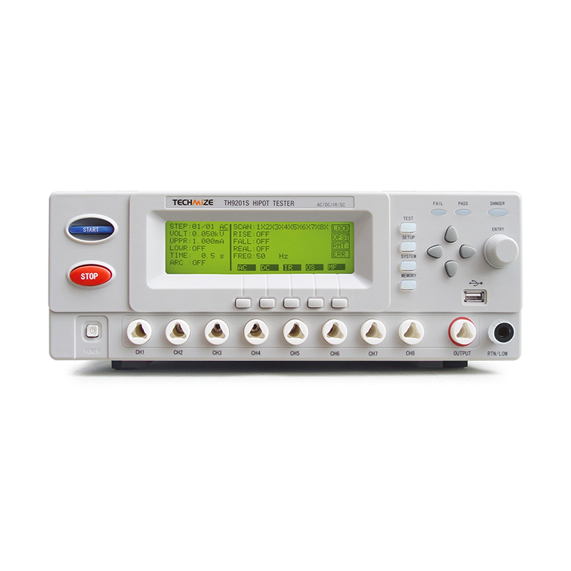
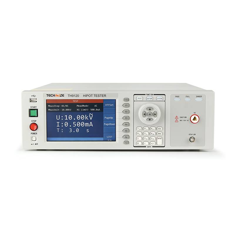
TH9201 Series AC/DC/IR Withstand Voltage Hipot Tester
AC Withstand Voltage Testing
AC withstand testing is widely used to verify the dielectric strength of insulation in products designed for AC mains or AC-connected systems. The TH9201 Series supports an AC output range from 0.05 kV to 5 kV, with an accuracy specification of ±(1.0% of reading + 5 digits). The test frequency can be selected at 50 Hz or 60 Hz according to the application requirement.
During an AC hipot test, the instrument applies the programmed voltage between the selected test points and monitors leakage current. If the current exceeds the defined limit or an arc is detected, the tester can identify the test as abnormal. This is useful for detecting breakdown paths that may not be visible during a visual inspection.
AC testing is particularly relevant to transformers, adapters, household electrical appliances, motors, power distribution components, and industrial control equipment. It can also be used for qualification testing of insulating materials and for routine production testing when the applicable standard calls for AC stress.
The available AC current test range varies by model. The series provides current measurement ranges reaching 0.01 mA to 30 mA on applicable configurations, while other versions support a range up to 20 mA. Selecting the correct model helps users match the instrument to the leakage-current limits and test requirements of the product under evaluation.
DC Withstand Voltage Testing
DC withstand testing is valuable when a stable electric field is required or when the test method specifies direct voltage. The series supports DC output up to 12.0 kV on applicable configurations. The DC current measurement range can extend from 0.1 μA to 10 mA, with other model configurations supporting up to 5 mA.
Compared with AC testing, DC testing can be advantageous for products with substantial capacitance, because the current associated with charging the product can be separated from the steady leakage current after the charging period. This makes programmable voltage rise time and voltage wait time especially important. The operator can control how quickly the voltage increases and can allow the product to stabilize before evaluating the final result.
DC testing is often used for capacitors, cables, filters, high-voltage assemblies, electronic modules, and products containing large capacitances. It may also be used for specialized transformer, winding, and insulation evaluations where a DC test is specified by the engineering procedure.
A key safety feature is automatic discharge after the test ends for DC withstand testing. A product under test may retain electrical charge after the high-voltage source is removed. The discharge function reduces this residual energy and helps protect operators, service personnel, and connected equipment. Appropriate external safety procedures, grounding, interlocks, and verification of zero voltage remain essential, but controlled discharge significantly improves the overall test process.
Insulation Resistance Measurement up to 10 GΩ
The insulation resistance function extends the instrument beyond a simple pass-or-fail dielectric test. The TH9201 Series provides an insulation test voltage range from 0.05 kV to 1 kV. Its resistance measurement range extends from 0.1 MΩ to 10 GΩ, covering a broad spectrum of applications from basic insulation screening to high-resistance evaluation.
At test voltages from 500 V to 1,000 V, the stated accuracy is ±(5% of reading + 5 digits) from 1 MΩ to 1 GΩ and ±(10% of reading + 5 digits) from 1 GΩ to 10 GΩ. At test voltages from 50 V to 500 V, the instrument supports measurement from 0.1 MΩ to 1 GΩ with an accuracy of ±(10% of reading + 5 digits). The stated current range for the resistance test is 10 nA to 10 mA.
These ranges allow engineers to investigate both obvious insulation faults and more subtle degradation. For example, a low resistance result may indicate a direct defect, while a gradually declining resistance trend may indicate moisture absorption, thermal aging, contamination, or mechanical stress.
Insulation resistance testing can be performed on transformer windings, motor windings, generator windings, cable insulation, connectors, printed assemblies, and insulating components. When used together with withstand voltage testing, it provides a more complete understanding of insulation performance.
The automatic discharge function also applies after the relevant DC insulation test. This is important because capacitive products and long cables can retain charge even after the measurement has ended. A controlled discharge sequence supports safer removal of the test item.
Arc Detection for Early Fault Identification
Arc detection is one of the important features that distinguishes a modern safety tester from a basic high-voltage power supply. A breakdown does not always appear as a large, sustained current increase. In some products, a brief or intermittent arc may occur across a small gap, contaminated surface, damaged coating, or sharp conductive point.
The TH9201 Series includes arc detection for AC and DC testing. The stated AC arc measurement range is 1 mA to 15 mA. The DC range varies by configuration and can reach 1 mA to 10 mA or 1 mA to 5 mA. The system is designed to detect arc events promptly so that the test can be stopped or identified as abnormal.
Arc detection improves product safety in several ways. It helps prevent a defective product from remaining under high-voltage stress for longer than necessary. It can reveal manufacturing defects that may not be identified by a simple leakage-current threshold. It can also support process improvement by showing that a particular assembly method, material, or cleaning process is creating intermittent discharge conditions.
In production environments, arc detection is especially helpful for products with complex insulation geometry. Transformers, coils, motor windings, connectors, and high-voltage assemblies may contain small spaces where an arc can develop before a conventional current limit is exceeded. Early detection allows the manufacturer to investigate the cause before the product reaches the customer.
Eight-Channel Matrix Scanning and Multi-Point Testing
Testing several points manually can be slow and inconsistent. Each connection requires operator attention, and repeated repositioning of test leads increases the risk of wiring errors. The eight-channel matrix scanner available in the series is designed to improve multi-point testing efficiency.
With an eight-channel matrix configuration, multiple test points can be selected according to a programmed sequence. This is useful when a product contains several windings, terminals, conductors, shield points, or insulation paths that must be evaluated in a defined order.
Matrix scanning can reduce manual intervention and help ensure that every required test is completed. It also supports repeatability because the same sequence can be used for every unit. In a production setting, this consistency is essential for comparing results between products, shifts, and production batches.
Typical scanning applications include transformer winding-to-winding tests, winding-to-core tests, motor lead inspections, multi-terminal component testing, cable assemblies, and electronic modules with several isolated circuits. The scanner may also be connected to fixtures designed specifically for a product family.
Users should select suitable high-voltage fixtures, connectors, insulation materials, spacing, and guarding for the intended voltage. The scanner increases test capability, but the complete test station must still be designed according to appropriate electrical safety principles.
Programmable Test Parameters
Different products require different test sequences. Applying high voltage instantly may cause unnecessary charging current or stress, while ending the test too quickly may fail to reveal a developing problem. The TH9201 Series provides adjustable timing parameters for controlled and repeatable testing.
Voltage rise time can be set from 0.1 seconds to 999 seconds. This permits a gradual increase for sensitive or capacitive products and supports rapid testing where appropriate. Voltage fall time is also adjustable from 0.1 seconds to 999 seconds, allowing the end of the test to be managed in a controlled way.
For DC testing, voltage wait time can be set from 0.1 seconds to 99.9 seconds. This waiting period allows the product to stabilize after the voltage has reached the target value. It is particularly useful when the initial charging current is significantly different from the steady-state leakage current.
The test time can be set from 0.3 seconds to 999 seconds. Short test times support high-throughput production, while longer durations can be used for engineering verification, qualification work, or special insulation studies.
These parameters make the instrument adaptable to different testing philosophies. A manufacturer can create a rapid screening sequence for every production unit and a more detailed engineering sequence for sample verification. The ability to save multiple procedures also reduces setup errors when the same tester is used for several product families.
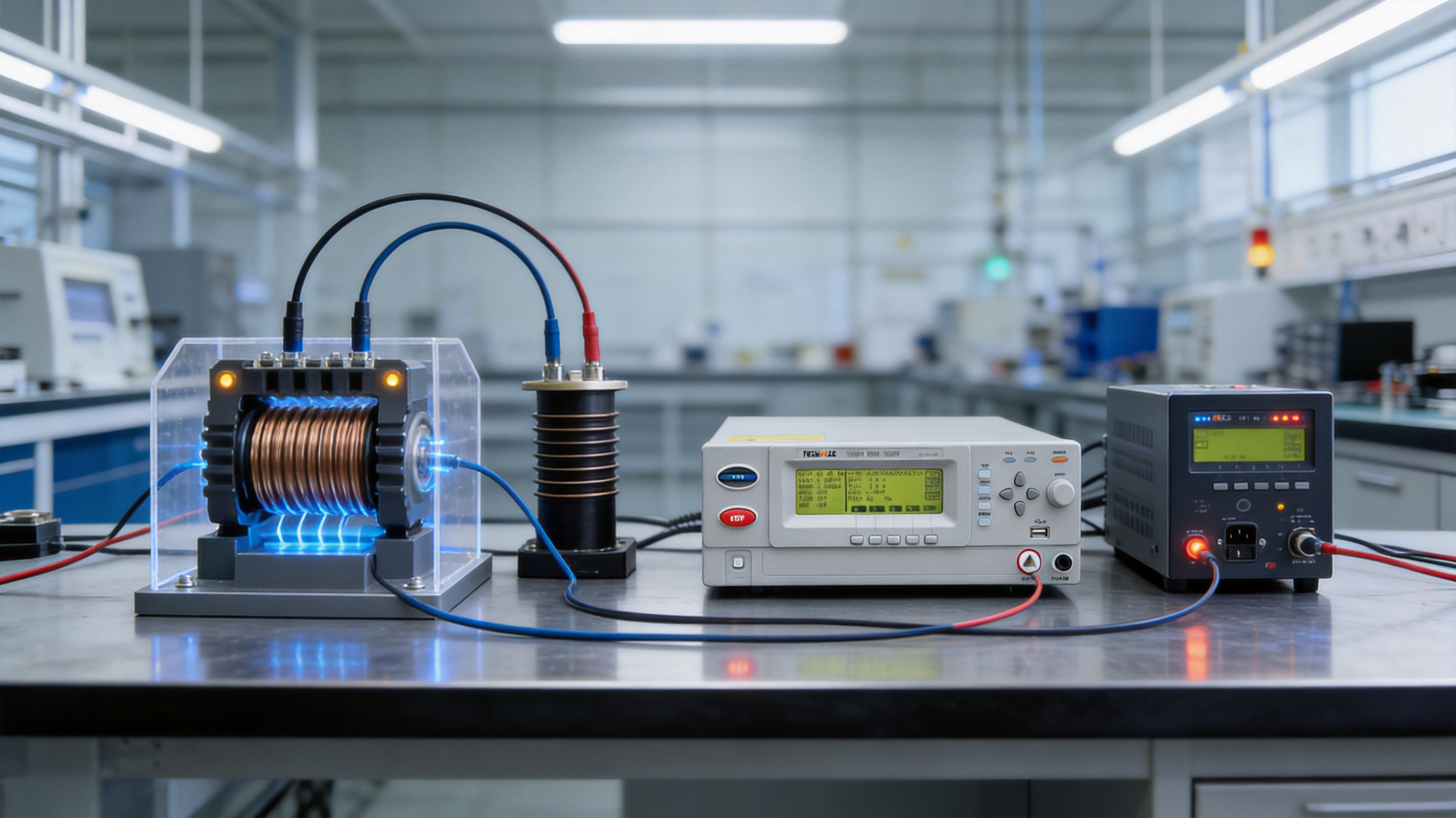
Memory, Records, and Test Procedure Management
Test data management is becoming increasingly important in modern manufacturing. A pass or fail result without a traceable procedure may not be sufficient for customer audits, internal quality reviews, or failure analysis. The TH9201 Series provides storage for 50 groups, with up to 100 test steps per group and a total storage capacity of 500 steps.
Each group can represent a product type, customer specification, production line, or engineering test. Within a group, multiple steps can define the required sequence. For example, one procedure may include an insulation resistance measurement, an AC withstand test between two points, a DC withstand test, and a final discharge step.
Stored procedures improve repeatability because operators do not need to enter every parameter manually for every batch. They also help reduce the risk of using the wrong voltage, duration, or current limit. In a busy factory, procedure-based operation is an important safeguard against human error.
Historical records can assist with trend analysis and troubleshooting. If a product family begins to show a gradual decline in insulation resistance, the quality team can investigate material moisture, assembly pressure, curing conditions, winding tension, soldering contamination, or changes in supplier components.
For full production traceability, users may connect the instrument to a host computer or manufacturing execution system through the available communication interfaces. The tester can then become part of a broader quality-control process rather than operating as an isolated bench instrument.
Operator Interface and Practical Usability
High-voltage equipment must be easy to operate correctly. A complicated interface can increase setup time and create opportunities for parameter mistakes. The TH9201 Series uses a 240 × 64 dot matrix LCD and a redesigned user interface to present test settings, status information, measurement values, and result indications in a clear format.
The display supports direct observation of important test conditions. Operators can review the selected test mode, output voltage, current, resistance, elapsed time, and test outcome. Clear information is particularly important when several test steps are executed automatically.
The compact design is suitable for laboratory benches and production stations where space is limited. A streamlined instrument can be positioned near a fixture, scanner, or control panel without requiring a large dedicated cabinet. Its design also supports easier integration into existing electrical safety test areas.
Usability includes more than the front-panel display. Adjustable timing, stored test groups, scanning, communication interfaces, and defined test sequences all reduce repetitive work. When these functions are configured properly, operators can focus on loading the product and confirming the result rather than manually controlling every stage of the high-voltage test.
Interfaces for Laboratory and Automated Production
The series includes RS232, USB, HANDLER, REMOTE I/O, and SCAN interfaces as standard. GPIB is available as an option. This group of interfaces supports a wide range of operating environments, from a standalone laboratory test to a fully integrated production system.
RS232 and USB can be used for communication with computers, data collection systems, or engineering software. These interfaces are useful for transferring results, controlling test parameters, and recording product identification together with the safety-test outcome.
The HANDLER interface is intended for connection to automated handling equipment. A handler can load a component, position it in the fixture, initiate the test, and remove the component after the result is received. This approach is valuable for high-volume testing where cycle time and consistent positioning are important.
REMOTE I/O supports external control and status exchange. It can be connected to a PLC, safety controller, signal tower, foot switch, or production-line control system. The SCAN interface supports the use of the matrix scanner and multi-point test fixtures.
GPIB remains useful in certain laboratory, calibration, and automated measurement systems. Its availability as an option allows customers with existing GPIB-based equipment to maintain compatibility with established control architectures.
When integrating the instrument into an automated station, the manufacturer should define safety interlocks, emergency-stop functions, access guarding, test-area warning indicators, and grounding arrangements. Communication control must never bypass the physical safety measures required for high-voltage operation.
Applications in Transformer Testing
Transformers require careful insulation evaluation because they contain several electrically isolated windings, layered insulation systems, core structures, terminals, and sometimes shielding elements. A defect in any part of the insulation system can reduce reliability or create a dangerous connection between circuits.
The TH9201 Series can be used for winding-to-winding and winding-to-core withstand tests, subject to the applicable test procedure and fixture design. The matrix scanner is especially useful when a transformer has multiple terminals or several winding combinations that must be tested sequentially.
Insulation resistance measurement can provide additional information about moisture, contamination, and the general condition of the transformer insulation. A stored multi-step procedure can ensure that every transformer is tested using the same sequence and limits.
In transformer production, the tester can be installed after winding, assembly, varnish treatment, or final inspection. The correct location depends on the manufacturer’s process-control strategy. Early testing can identify defects before additional value is added, while final testing confirms the completed unit.
Applications in Motors and Generator Windings
Motor and generator windings are exposed to thermal cycling, vibration, electrical surges, mechanical movement, and contamination. Their insulation systems must therefore be evaluated carefully during manufacturing and maintenance.
Withstand testing can identify weak enamel, damaged slot liners, incorrect winding placement, insufficient separation, and assembly defects. Insulation resistance testing can reveal moisture or contamination that may not be visible externally.
Testing several winding leads in a defined sequence is easier when the instrument is connected to a suitable multi-point fixture. The operator or automated system can select the required terminals, apply the programmed test, measure the result, discharge the product, and proceed to the next step.
For repair workshops, the tester can help compare the condition of a winding before and after cleaning, drying, rewinding, or varnish treatment. Test results should always be interpreted together with the motor’s rated voltage, insulation class, service history, temperature, and applicable maintenance standard.
Applications in Electronic Components and Assemblies
Electronic products often combine low-voltage control circuits, mains-connected circuits, metal frames, shields, filters, capacitors, and communication interfaces. The insulation barriers between these areas must be verified during development and production.
The TH9201 Series can support testing of capacitors, inductors, power supplies, adapters, control boards, connectors, cable assemblies, and other electronic components. AC or DC withstand testing can be selected according to the product design and applicable requirements, while insulation resistance testing helps identify conductive contamination and assembly defects.
For products with capacitive input filters, programmable rise time and DC wait time are useful because the initial charging behavior can otherwise affect the measured current. A controlled sequence gives the product time to stabilize before the final evaluation.
In component manufacturing, automated interfaces and stored procedures help maintain uniform testing across large batches. The instrument can communicate the result to a production controller, while the test group can be selected according to the component model or work order.
Advantages over Basic or Single-Function Testers
A basic hipot tester may provide only a high-voltage output and a current trip function. Such equipment can be useful for simple applications, but it may require additional instruments, manual connections, and separate procedures for insulation resistance measurement and data management.
The TH9201 Series offers a broader integrated solution. AC withstand, DC withstand, insulation resistance, arc detection, discharge, programmable timing, memory, scanning, and automation interfaces are combined in one product family. This reduces equipment duplication and simplifies the organization of a safety-testing station.
The adjustable voltage rise and fall times provide better control than fixed-speed instruments. The DC waiting period allows more meaningful evaluation of capacitive products. The wide resistance range, reaching up to 10 GΩ, supports both routine production screening and more detailed insulation evaluation.
The eight-channel matrix scanner, where included, offers an efficiency advantage for multi-point products. Instead of manually moving leads for every measurement, the test sequence can be organized through a fixture. This reduces operator workload and improves consistency.
Data storage for 500 test steps is another important advantage. Operators can manage several product procedures without repeatedly entering all parameters. The availability of RS232, USB, HANDLER, REMOTE I/O, and SCAN interfaces also gives the series greater flexibility for automation than instruments designed only for standalone use.
Finally, safety-oriented functions such as arc detection and fast discharge address practical risks that may not be covered by a simple voltage source. These features help protect both the product and the operator while improving the quality of the test result.
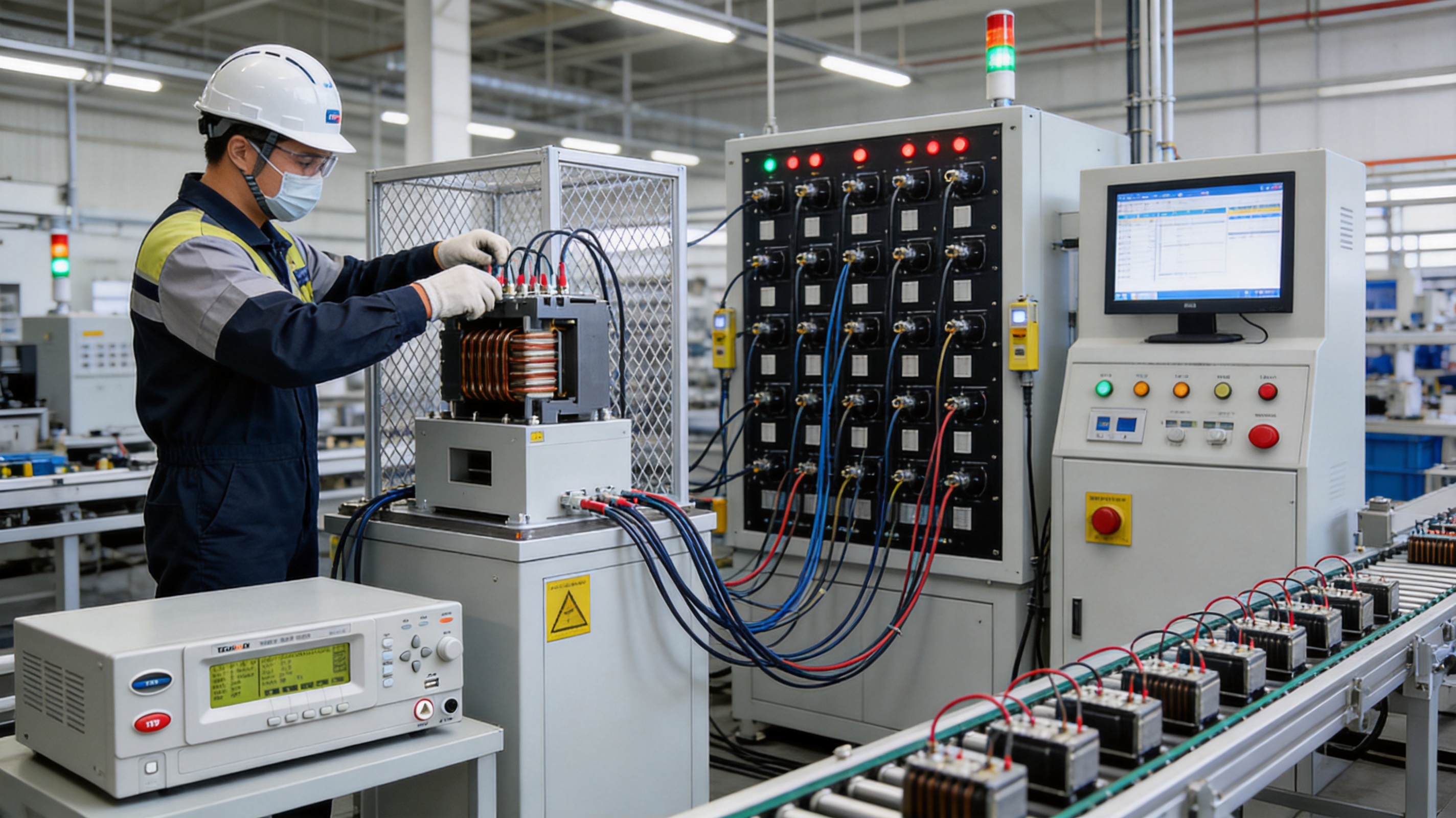
Manufacturing Strengths and Engineering Capabilities
JIANGSU BAISHENG INDUSTRIAL CO., LTD. was established as a technology-driven enterprise specializing in laboratory equipment and safety testing instruments. Its development approach combines product engineering, research and development, manufacturing coordination, and international trade expertise.
The company’s history began with an electronic testing research and development studio in 2013. The founding team brought technical experience in laboratory equipment and safety compliance testing. In 2016, the organization developed into an enterprise with an independently developed production line and introduced laboratory equipment with independent intellectual property rights.
This technical background is important for a high-voltage safety tester. A reliable instrument requires more than a housing and a transformer. It requires controlled high-voltage generation, stable measurement circuits, carefully designed protection, safe discharge paths, dependable switching, software logic, user-interface design, and suitable communication architecture.
In 2019, the company adopted a technology-plus-trade development strategy and increased research and development investment. This helped connect product engineering with the requirements of international customers, different industrial sectors, and varied testing environments.
The company further improved its quality-management system in 2022, with products undergoing rigorous technical-specification certification and evaluation. By 2025, its development activities continued to emphasize intelligent functions, digitalization, and expanded application scenarios.
Advanced Manufacturing Process for Electrical Safety Instruments
Manufacturing a professional hipot tester requires disciplined control at every stage. The process begins with a review of the electrical architecture, required output range, measurement accuracy, protection strategy, enclosure design, and intended operating environment.
High-voltage components must be selected according to insulation strength, thermal performance, creepage distance, clearance, current capability, and long-term reliability. The arrangement of high-voltage wiring and terminals is also important because unnecessary proximity can create leakage or unwanted discharge paths.
Measurement circuits require stable reference components, appropriate filtering, controlled signal routing, and calibration procedures. The instrument must distinguish between normal charging current, steady leakage current, and abnormal current caused by insulation breakdown or arcing.
Mechanical manufacturing is equally important. The enclosure must protect internal circuits, support safe operation, and provide appropriate access to displays, controls, connectors, and test leads. Internal barriers, insulation supports, grounding points, and cable routing should be designed to reduce the possibility of accidental contact or unwanted coupling.
Assembly technicians must follow defined procedures for wiring, fastening, soldering, connector installation, insulation placement, and labeling. High-voltage products benefit from clear process documentation because small assembly differences can influence safety performance and measurement repeatability.
Software and firmware are developed to coordinate voltage ramping, test timing, current monitoring, resistance measurement, arc detection, result evaluation, discharge, memory functions, and external control. Reliable software sequencing is essential because the instrument must respond quickly to abnormal conditions while maintaining the programmed test profile.
Before shipment, the finished tester should undergo functional checks, output verification, current and resistance measurement checks, interface testing, display inspection, protective-function testing, and extended operation evaluation. This multi-stage approach supports consistent product quality and helps identify issues before the instrument reaches the customer.
Quality Control and Calibration Considerations
Electrical safety testers must produce results that users can trust. Calibration is therefore an essential part of the instrument life cycle. The test voltage, measured current, insulation resistance, timing, and fault thresholds should be checked using suitable reference equipment and documented procedures.
Accuracy specifications provide a basis for evaluating measurement performance. For the TH9201 Series, withstand-voltage measurement accuracy is stated as ±(1.0% of reading + 5 digits), while insulation resistance accuracy depends on the selected voltage and resistance range.
Users should establish a calibration interval based on operating frequency, environmental conditions, internal quality requirements, and applicable regulatory or customer specifications. Instruments used continuously on a production line may require more frequent verification than units used occasionally in a controlled laboratory.
Daily or periodic operational checks are also valuable. These may include inspecting test leads, confirming the condition of the fixture, checking grounding, verifying interlocks, examining discharge behavior, and using a known reference device to confirm that the tester produces an expected result.
Calibration does not replace safe operation. A properly calibrated instrument must still be installed in a suitable test area with guarded high-voltage access, warning indicators, emergency-stop capability, and trained personnel.
Designing a Safe Test Station
The tester should be used in a controlled area where unauthorized personnel cannot access the product under test. A safety enclosure or interlocked test fixture is recommended for production applications. The test area should include clear warning labels and visual indicators showing when high voltage is active.
Test leads and fixtures must be rated for the maximum voltage and current of the application. The spacing between conductive points should be appropriate for the voltage, pollution level, material group, and intended environment. Sharp edges and loose strands should be avoided because they may create unintended electric-field concentrations.
The product under test should be positioned securely. Movement during a high-voltage test can cause intermittent contact, arcing, or incorrect results. For automated systems, the fixture should confirm that the product is properly seated before the tester receives the start command.
Grounding is another essential consideration. The tester, fixture, enclosure, and product reference points should be connected according to the approved safety design. The discharge path must be suitable for the energy stored by the product, especially when testing capacitors, cables, and high-capacitance assemblies.
Operators should be trained to understand the difference between the test result and the safety condition of the station. They should never touch the product, fixture, or exposed test point while a test is active or before residual voltage has been verified as safe.
Using the Instrument in Production
A reliable production test begins with a controlled work instruction. The instruction should identify the product model, fixture, connection points, test sequence, voltage, current or resistance limits, timing parameters, pass/fail criteria, and required records.
The operator should inspect the tester and fixture before beginning the batch. Test leads should be checked for damage, the correct procedure should be selected from memory, and the product should be connected according to the work instruction.
For high-volume applications, the HANDLER and REMOTE I/O interfaces can coordinate the tester with the production line. A controller can verify that the fixture is closed, select a test program, start the sequence, receive the result, and route the product to the appropriate next process.
When several tests are required, a programmed group can reduce the possibility of skipping a step. For example, a product may first undergo insulation resistance testing, followed by AC withstand testing, DC withstand testing, and final discharge. The actual sequence should be determined by the product design and applicable standard.
Production data should be linked to product identification wherever possible. Serial numbers, lot numbers, operator information, fixture identification, and test results can provide valuable traceability. If a failure occurs, stored information can help determine whether the problem is isolated or part of a broader process trend.
Engineering and Research Applications
In research and development, the instrument can be used to compare insulation materials, evaluate prototypes, investigate design margins, and confirm the effect of manufacturing changes. Adjustable rise time and test duration are helpful when engineers need to study how a product responds to different electrical stress profiles.
For prototype transformers or motors, the tester can support early verification of winding insulation before the design enters mass production. For electronic assemblies, it can help confirm separation between primary and secondary circuits, chassis, shields, and accessible conductive parts.
The memory function allows engineers to save repeatable test methods for design comparisons. Communication interfaces can also support automated experiments in which the test result is recorded together with temperature, humidity, material type, or construction details.
Arc detection can provide useful insight during design validation. If a prototype passes a current-limit test but produces intermittent arcs, the design team may need to review spacing, edge treatment, material selection, potting, bonding, or contamination control.
Environmental and Operating Considerations
High-voltage measurements can be affected by environmental conditions. Moisture, dust, temperature, surface contamination, and cable arrangement may influence leakage current and insulation resistance. Test results should therefore be interpreted in the context of the environment in which they were obtained.
Products should be clean and dry unless the purpose of the test is specifically to evaluate performance under a particular environmental condition. If a product contains capacitive elements, the operator should allow suitable settling time and confirm that the discharge function has completed before handling it.
Fixtures should be maintained regularly. Dust and residue can create unintended leakage paths, while worn insulation can reduce the safety margin of the test station. Periodic cleaning, visual inspection, torque checks, and replacement of damaged cables are practical ways to protect measurement quality.
Users should consult the instrument manual and the relevant product standard for installation, operating temperature, humidity, altitude, storage, and maintenance requirements. The stated performance of a precision instrument assumes that it is used within its specified operating conditions.
Recommended Selection Approach
When selecting a TH9201 Series configuration, the first consideration is the required test type. If the application needs only AC withstand testing, the basic configuration may be sufficient. If DC withstand, insulation resistance, or arc detection is required, the selected model must support those functions and the necessary current ranges.
The second consideration is voltage. The series supports AC testing up to 5 kV, DC testing up to 12.0 kV on applicable models, and insulation resistance testing from 0.05 kV to 1 kV. The required voltage should be determined by the product rating, applicable standard, customer specification, and engineering safety margin.
The third consideration is the test current or resistance range. Products with very low leakage limits may require a configuration with appropriate sensitivity, while high-capacitance products may require a model capable of handling the expected charging and leakage behavior.
The fourth consideration is the number of test points. Products with multiple terminals or repeated connection combinations may benefit substantially from the eight-channel matrix scanner. A single-point product may not need this option.
Finally, users should review automation requirements. RS232, USB, HANDLER, REMOTE I/O, and SCAN are standard interfaces, while GPIB is available as an option. The correct interface combination depends on the existing factory control system and the desired level of data integration.
| Function | Available Capability | Typical Benefit |
|---|---|---|
| AC withstand voltage | 0.05 kV to 5 kV, 50 Hz or 60 Hz | Verification of dielectric strength in AC-connected products |
| DC withstand voltage | 0.05 kV to 12.0 kV on applicable configurations | Controlled testing of capacitive and high-voltage assemblies |
| Insulation resistance | 0.1 MΩ to 10 GΩ | Detection of contamination, moisture, aging, and insulation defects |
| Arc detection | AC and DC detection ranges according to model | Early identification of intermittent or developing discharge |
| Matrix scanning | Eight-channel scanner on applicable models | Efficient multi-point and multi-terminal testing |
| Programmable timing | Rise and fall time up to 999 seconds; test time up to 999 seconds | Repeatable test sequences for different product types |
| Data storage | 50 groups, 100 steps per group, 500 steps total | Procedure management and improved production consistency |
| Communication | RS232, USB, HANDLER, REMOTE I/O, SCAN; optional GPIB | Laboratory control and automated production integration |
Why the Series Is Suitable for Global Industrial Use
Industrial customers often require more than a technically capable instrument. They need stable communication, product customization, documentation, and continuing support. The manufacturer’s combined engineering and international trade experience allows it to serve customers with different application requirements and purchasing procedures.
The company’s focus on customized laboratory equipment solutions is valuable when a standard bench tester must be adapted to a special fixture, connector arrangement, voltage sequence, data format, or automated line. Customization may include test-program development, scanning arrangements, communication integration, fixture coordination, and application guidance.
A dedicated research and development team also supports continuous improvement. As electrical products become smaller, more integrated, and more digitally controlled, safety testers must respond to new test sequences, higher production speeds, greater data requirements, and more complex insulation systems.
The company’s stated values, centered on precision, long-term innovation, integrity, and mutually beneficial cooperation, align with the demands of safety-critical measurement equipment. For customers, this means that product selection can be supported by technical communication rather than being limited to a catalogue specification.
Best Practices for Reliable Results
Use the correct test voltage and acceptance limit for the product. A higher voltage is not automatically a better test, and an incorrect limit can produce misleading results or damage the product under evaluation.
Keep the test fixture clean and dry. Surface contamination may cause leakage current that is unrelated to the product, while worn insulation may create a safety hazard.
Use a controlled connection sequence. The product should be connected before the high-voltage test begins, and it should be removed only after the test has ended and the discharge process has completed.
Allow appropriate settling time for capacitive products. The programmable DC wait period can help distinguish charging current from steady-state leakage.
Record environmental conditions when comparing results over time. Temperature and humidity can significantly affect insulation resistance, especially in porous or moisture-sensitive materials.
Verify the calibration status of the instrument and inspect the test leads before use. Measurement confidence depends on the complete test system, not only on the main instrument.
Use stored procedures for repeat production work. This minimizes manual entry errors and helps ensure that all operators use the same test parameters.
Investigate intermittent failures rather than dismissing them as operator error. Arc detection and historical records may reveal a developing process problem, fixture defect, or material issue.
Q&A
What is the main purpose of the TH9201 Series?
The series is designed for electrical safety testing, including AC withstand voltage, DC withstand voltage, insulation resistance, and arc detection. It is intended for electrical equipment, electronic components, transformer windings, motor windings, insulating materials, and automated production applications.
What is the maximum AC test voltage?
The AC output range is 0.05 kV to 5 kV. The specified accuracy is ±(1.0% of reading + 5 digits), and 50 Hz or 60 Hz can be selected according to the application.
What is the maximum DC test voltage?
Applicable configurations support DC output up to 12.0 kV. The exact model selection should be confirmed according to the required current range and product test procedure.
What is the insulation resistance measurement range?
The resistance measurement range is 0.1 MΩ to 10 GΩ. The accuracy depends on the selected test voltage and resistance range.
Why is arc detection important?
Arc detection identifies abnormal discharge events that may occur before a large leakage-current increase appears. It can help reveal weak insulation, sharp-edge field concentration, contamination, and intermittent breakdown conditions.
Does the tester discharge the product after testing?
Yes. The series includes a discharge function after DC withstand and applicable insulation tests. Users must still follow the approved safety procedure and verify that the product is safe before touching it.
What is the purpose of the eight-channel matrix scanner?
The scanner allows multiple test points to be selected and tested in a programmed sequence. It is useful for transformers, motors, cable assemblies, multi-terminal components, and products requiring repeated point-to-point measurements.
Can the tester be used on an automated production line?
Yes. The series includes HANDLER, REMOTE I/O, SCAN, RS232, and USB interfaces as standard. GPIB is available as an option. These interfaces support communication with PLCs, handlers, computers, fixtures, and production-control systems.
How many test procedures can be stored?
The instrument can store 50 groups, with up to 100 test steps per group and 500 steps in total. This supports multiple product models and multi-step safety-test sequences.
Which industries can use this instrument?
Typical users include transformer manufacturers, motor and generator producers, electronic-component factories, power-supply manufacturers, appliance producers, cable and connector companies, laboratories, repair facilities, and research departments.
How should a customer choose between the model configurations?
Selection should be based on required AC and DC voltage, current range, insulation resistance range, arc detection requirements, number of test points, scanner needs, and automation interfaces. The manufacturer can assist in matching the configuration to the product and production process.
Is the tester suitable for laboratory and production use?
Yes. Its adjustable timing, memory, LCD interface, measurement functions, and communication options support laboratory work, while its stored procedures, scanner, handler interface, and remote I/O support production automation.
What safety precautions are necessary?
The tester should be installed in a controlled and guarded area with suitable grounding, interlocks, warning indicators, emergency-stop functions, rated fixtures, and trained operators. The product must not be touched during testing or before residual voltage has been safely discharged and verified.
Conclusion
The TH9201 Series AC/DC/IR Withstand Voltage Hipot Tester is a flexible platform for modern electrical safety testing. It combines AC and DC withstand testing with insulation resistance measurement, arc detection, controlled discharge, programmable timing, data storage, multi-point scanning, and automation interfaces.
Its broad voltage and resistance capabilities allow it to serve transformers, motors, generators, electronic components, power supplies, cable assemblies, insulating materials, and finished electrical products. Compared with a basic single-function tester, it provides a more complete and efficient approach to insulation verification and production quality control.
The series is also supported by a manufacturer with a technology-driven development history, an engineering-focused research and development team, independent production experience, international trade capability, and a commitment to customized laboratory and safety-testing solutions. Its manufacturing approach combines electrical design, high-voltage protection, measurement accuracy, software control, mechanical construction, quality inspection, and application support.
For organizations seeking to improve electrical safety, strengthen production consistency, and integrate test results into modern manufacturing systems, the TH9201 Series offers a practical foundation. When correctly configured and installed with suitable safety controls, it can help manufacturers identify insulation defects earlier, protect operators, reduce manual testing effort, and build greater confidence in the reliability of electrical products.
References
IEC 61010-1, Safety Requirements for Electrical Equipment for Measurement, Control, and Laboratory Use.
IEC 61180, High-Voltage Test Techniques for Low-Voltage Equipment.
IEC 60270, High-Voltage Test Techniques: Partial Discharge Measurements.
IEEE Std 43, Recommended Practice for Testing Insulation Resistance of Electric Machinery.
International Electrotechnical Commission, General Principles of Electrical Insulation Coordination.
Manufacturer technical specifications for the TH9201 Series AC/DC/IR Withstand Voltage Hipot Tester.
Manufacturer quality and product-development information for laboratory and electrical safety testing equipment.
Product: TH9201 Series AC/DC/IR Withstand Voltage Hipot Tester

PREV:Precision Ground Bond Testing for Safer, More Reliable Electrical Products
NEXT:High-Vacuum Ion Beam Etching and Deposition for Precision Surface Engineering
NEXT:High-Vacuum Ion Beam Etching and Deposition for Precision Surface Engineering
Interested in cooperation or have questions?
Featured Products
Related products
Quick Link
Contact Information
- Tel: +86-13861043568
- E-mail: 1840784112@qq.com
- Add: Tianting District, Changzhou City, Jiangsu Province, China, No. 6 Hecircuit
Scan Code
Copyright © JIANGSU BAISHENG INDUSTRIAL CO., LTD.
All Rights Reserved. Privacy Custom Precision Laboratory Testing Equipment Manufacturers
