 English
 Español
NEWS
NEWS
NEWS
NEWS
NEWS
NEWS
NEWS
NEWS
NEWS
NEWS
NEWS
NEWS
NEWS
NEWS
NEWS
NEWS

Deng Xinyi — Product After-Sales Support Specialist
Home / Author / Deng Xinyi — Product After-Sales Support Specialist / Precision Ground Bond Testing for Modern Electrical Safety and Automated Quality Control
Precision Ground Bond Testing for Modern Electrical Safety and Automated Quality Control
Content
- 1 The Role of Ground Bond Testing in Electrical Safety
- 2 TH9410A Series Product Overview
- 3 Key Technical Advantages
- 4 Applications Across Multiple Industries
- 5 Advantages in Laboratory and Production Environments
- 6 Technical Specification Summary
- 7 Manufacturing and Engineering Strengths
- 8 Comparison with Basic or Less Specialized Test Equipment
- 9 Recommended Implementation Practices
- 10 How the Instrument Supports Continuous Improvement
- 11 Responsible Use and Technical Boundaries
- 12 Why the TH9410A Series Is a Practical Long-Term Choice
- 13 Q&A
- 13.1 What is a ground bond test?
- 13.2 What is the maximum current of the TH9410A?
- 13.3 Why is four-terminal testing important?
- 13.4 What resistance range can the instrument measure?
- 13.5 Can the resistance limits be programmed?
- 13.6 How long can a test run?
- 13.7 Is the tester suitable for automated production systems?
- 13.8 How many test procedures can be stored?
- 13.9 What industries can use the TH9410A Series?
- 13.10 Does ground bond testing replace insulation or dielectric testing?
- 13.11 What display does the instrument use?
- 13.12 What input power options are available?
- 13.13 What should be considered when selecting test limits?
- 13.14 What is the manufacturer’s main strength?
- 14 Conclusion
- 15 References
- 16 Product: TH9410A Series Backlit LCD Display Ground Bond Tester

Electrical safety testing is a fundamental requirement in the design, manufacture, repair, and certification of products that connect to the power grid. Household appliances, industrial machinery, medical devices, transformers, motors, lighting equipment, electronic assemblies, and new energy vehicles all depend on effective protective grounding. If a metal enclosure or accessible conductive part becomes energized because of an insulation fault, the grounding system must provide a low-resistance path for fault current. This path allows protective devices to operate quickly and reduces the possibility of electric shock, fire, equipment damage, or regulatory nonconformity.
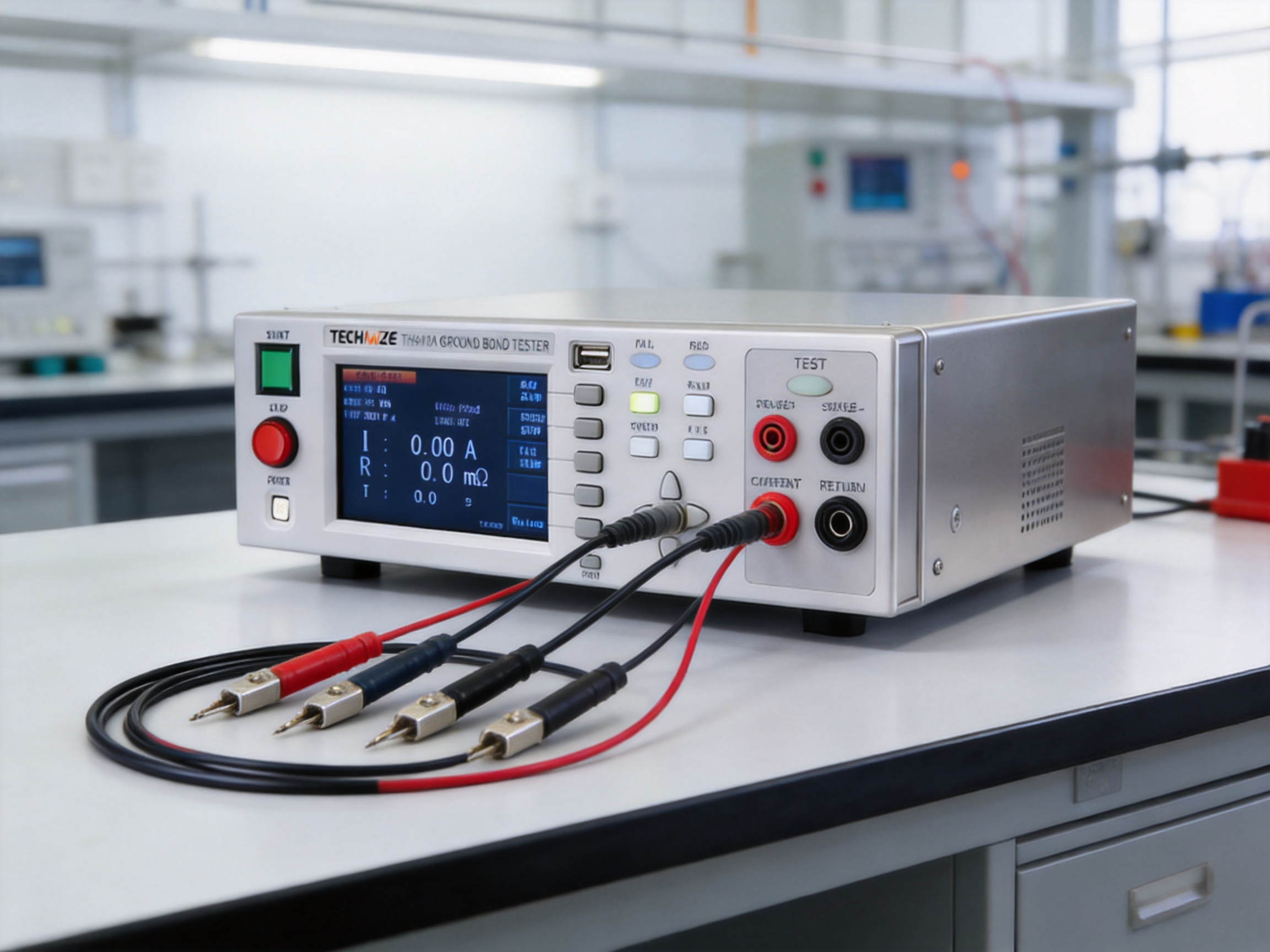
The TH9410A Series Backlit LCD Display Ground Bond Tester is designed to verify this critical protective path. It combines adjustable high-current output, low-resistance measurement, four-terminal testing, programmable test timing, data storage, safety controls, and production-line integration features in one instrument. Its principal model, the TH9410A, supports test currents from 1.00 A to 45.00 A and measures grounding resistance across a range extending to 600 milliohms, subject to the relationship between test current and the maximum permitted resistance.
More than a basic resistance meter, the instrument is a dedicated electrical safety tester intended for repeatable and controlled ground bond verification. Its backlit TFT-LCD provides a clear interface for operators, while its independent power amplifier circuit helps maintain stable current output under changing load conditions. The design is appropriate for laboratory evaluation, incoming inspection, production testing, quality assurance, service work, and automated test systems.
The Role of Ground Bond Testing in Electrical Safety
A protective earth or grounding conductor is intended to carry fault current safely away from exposed conductive surfaces. Under normal conditions, the grounding path may carry little or no current. During an insulation failure, however, the path must conduct enough current to activate a fuse, circuit breaker, residual-current device, or other protective mechanism. A high-resistance connection can prevent the protective device from operating as intended.
Ground bond testing applies a controlled current through the protective conductor and measures the voltage drop across the path. Resistance is then determined according to Ohm’s law. The test is especially important for products containing metal chassis, frames, covers, brackets, terminals, heat sinks, or other conductive parts that users may touch.
Typical sources of unwanted grounding resistance include loose terminals, poorly crimped connectors, oxidized contact surfaces, insufficient welds, undersized conductors, damaged cables, incorrect assembly, and contamination between contact points. These defects may not be visible during a visual inspection. A properly configured ground bond test can identify them before a product reaches the customer.
The test current must be high enough to produce a meaningful voltage drop and to simulate demanding fault conditions. At the same time, the instrument must control current accurately, measure very small resistance values, and prevent operator error. These requirements distinguish a professional ground bond tester from a general-purpose multimeter or a simple continuity checker.
TH9410A Series Product Overview
The TH9410A Series is built for applications that require both high-current output and low-resistance measurement. The TH9410A provides an adjustable current range of 1.00 A to 45.00 A. The related TH9411A model supports a range of 1.00 A to 32.00 A. This product family allows users to select an instrument that matches the current requirements, test standards, production volume, and application profile of a particular facility.
The tester measures grounding resistance from zero to 600 milliohms under the stated operating conditions. The maximum measurable resistance depends on the selected current, with the specification expressed as Rmax less than or equal to 6 divided by the set current. When the current is below 10 A, the maximum resistance can reach 600 milliohms. This relationship is important because it reflects the practical interaction between current capacity, measurement range, and instrument output capability.
The four-terminal test mode is a major technical feature. In a conventional two-wire measurement, the resistance of test leads, connectors, clips, and contact interfaces can be included in the result. This additional resistance may be significant when the device under test has a resistance of only a few milliohms or tens of milliohms. Four-terminal measurement separates the current path from the voltage-sensing path, allowing the instrument to measure the voltage drop at the test points with much less influence from lead resistance.
By reducing the effects of the measurement fixture, the four-terminal configuration improves confidence in low-resistance readings. It is particularly valuable for production fixtures, long test cables, busbars, protective earth terminals, welded joints, and other applications in which connection resistance might otherwise distort the result.
The front and rear panel output holes support flexible installation. A user can operate the tester from the front panel in a laboratory or maintenance environment, or connect it through the rear panel when the instrument is installed in a test rack, standard chassis, or automated production station. This adaptability helps reduce the need for separate instrument designs for laboratory and manufacturing applications.

TH9410A Series Backlit LCD Display Ground Bond Tester
Key Technical Advantages
Adjustable High-Current Output
The adjustable output current from 1.00 A to 45.00 A gives the TH9410A a broad application range. Low-current settings can be used for products or assemblies with modest grounding requirements, while higher settings provide stronger verification for heavy-duty equipment, industrial components, and protective conductor systems that require more demanding testing.
The current setting resolution is 0.01 A, and the readback resolution is also 0.01 A. This level of adjustment allows users to establish consistent test conditions and maintain repeatability between production units. It also assists engineers in creating test procedures that correspond closely to internal quality requirements or applicable safety standards.
Compared with fixed-current instruments, an adjustable tester offers greater flexibility when one facility handles several product categories. A manufacturer may use one current profile for a household appliance, another for a motor assembly, and a higher setting for an industrial cabinet or vehicle component. The same instrument can support these different requirements without changing the fundamental test platform.
Low-Resistance Measurement
The resistance measurement range extends to 600 milliohms, with a resolution of 1 milliohm in the specified lower-current range and 0.1 milliohm in other specified ranges. The resistance accuracy is rated at plus or minus 2 percent of reading plus 2 digits. These specifications support the evaluation of protective grounding paths where small changes in resistance may indicate a meaningful assembly or material problem.
Low resistance does not automatically mean safe resistance, because the acceptable value depends on the product design, conductor size, test current, applicable standard, and test location. The TH9410A therefore provides programmable upper and lower limits. The upper limit can be set from zero to 600 milliohms, while the lower limit can also be defined within the available range and must remain below the upper limit. This allows the tester to determine whether a measured result is within the engineering window established by the user.
Independent Power Amplifier Circuit
The independent power amplifier circuit drives the current output separately from the instrument’s measurement and control functions. This architecture is designed to reduce the influence of power supply fluctuations and load variations on the test current. Stable current output is essential because the accuracy and repeatability of a resistance measurement depend directly on the consistency of the applied current.
In practical production environments, the load may vary from one unit to the next. A tightly assembled product may present a different impedance profile from a unit with a longer conductor, a different contact surface, or a slightly altered mechanical connection. The independent amplifier helps the tester respond predictably to these changes rather than allowing them to cause uncontrolled variations in output.
This feature also supports more reliable automatic judgment. If current fluctuates substantially, a borderline product could produce inconsistent pass or fail decisions. A stable output stage reduces this risk and helps quality teams distinguish real product differences from test-system variation.
Four-Terminal Measurement Architecture
The four-terminal method is one of the most important differences between a professional ground bond tester and a basic resistance measurement device. Two terminals supply the programmed current, while two separate sensing terminals measure the voltage drop across the selected section of the grounding path. Because the sensing circuit draws very little current, the voltage measurement is less affected by the resistance of the current leads.
This arrangement is well suited to low-resistance measurements where a few milliohms can influence the result. It also helps when the test station uses long cables, interchangeable fixtures, spring probes, alligator clips, or other connection hardware. Although proper fixture design and contact maintenance remain necessary, the four-terminal configuration provides a stronger technical foundation for accurate measurement.
Backlit TFT-LCD Interface
The 480 by 272 dot backlit TFT-LCD provides clear visibility of settings, measured values, test status, limit conditions, and operating prompts. A backlit display is useful in laboratories, factory areas, equipment rooms, and test stations where ambient illumination may vary during different shifts or production conditions.
Clear presentation is not merely a convenience. Test operators must be able to verify the selected current, resistance limits, test time, and pass or fail state before accepting a result. A readable interface reduces the possibility of selecting an incorrect test file or misinterpreting a displayed value. It also shortens training time for new operators and improves consistency across multiple workstations.
Programmable Test Time
The test time range extends from 0.5 seconds to 999.9 seconds, with a resolution of 0.1 seconds. A setting of zero enables continuous operation. This range exceeds the short-duration requirements common in routine inspections and gives engineers the flexibility to perform longer verification cycles when required by a product design or internal validation plan.
Shorter test times can support high-throughput manufacturing when the product and applicable procedure permit rapid testing. Longer durations may be selected during design verification, process qualification, troubleshooting, or special inspections. The timing accuracy is specified as plus or minus 0.1 percent plus 0.05 seconds, providing a defined basis for repeatable procedures.
Safety Lock and Keyboard Lock Functions
High-current testing requires deliberate operation. The safety lock function is designed to prevent accidental activation of the test state, while the keyboard lock function helps prevent unintended changes to operating parameters. Together, these controls help protect operators, preserve test consistency, and reduce the likelihood of unauthorized adjustment on a production line.
In a controlled workstation, a supervisor or process engineer can configure the current, limits, and timing, then lock the keyboard so operators cannot accidentally alter the procedure. The safety lock provides an additional layer of control by ensuring that testing does not begin unexpectedly. These features are especially useful when several instruments are operated in parallel or when the tester is integrated into a semi-automatic fixture.
Internal Data Storage
The tester can store up to 20 test files, with each file containing up to 20 test steps. This capability enables users to organize procedures for different products, product variants, inspection stages, or customer requirements. Stored test files help ensure that operators use an approved sequence rather than entering settings manually for every unit.
Structured test storage can also improve traceability within a production process. A facility may create separate files for a motor, transformer, appliance, lighting assembly, medical device, or vehicle component. Each file can reflect the appropriate current, resistance limits, test duration, and step order. While the tester’s internal storage is not a substitute for a complete factory quality database, it provides a practical foundation for repeatable local test management.
Applications Across Multiple Industries
Household Appliances
Household appliances often contain metal frames, heating elements, motors, compressors, switches, and protective earth conductors. Products such as washing machines, refrigerators, ovens, water heaters, and cooking equipment may experience vibration, thermal cycling, humidity, and repeated mechanical movement during service life. Each factor can affect the integrity of grounding connections.
The TH9410A can be used during prototype evaluation, assembly-line testing, final inspection, and service investigation. A manufacturer can establish resistance limits for the protective earth path and use the tester to identify loose terminals, insufficient crimping, defective fasteners, or poor bonding between metal sections. The programmable time and stored test files are useful when one production line handles multiple appliance models.
Transformers and Motors
Transformers and motors contain conductive frames, mounting structures, terminal systems, shields, and sometimes multiple grounding points. Their manufacturing processes may include winding, pressing, welding, coating, bolting, and enclosure assembly. Ground bond verification can detect problems introduced at several of these stages.
For motors, vibration resistance and mechanical durability are especially important. A ground connection that passes a basic continuity check may still have an undesirable resistance level or may depend on an unreliable contact surface. High-current ground bond testing provides a more demanding evaluation of the completed assembly.
Transformers may require inspection of tank grounds, core grounding systems, cabinet connections, and other conductive structures. The tester’s wide current range and low-resistance measurement capabilities allow engineers to select suitable conditions for different transformer sizes and configurations.
Electric Heating Equipment and Lighting
Electric heating devices can contain high-power elements located near metal housings. Lighting products may include metal bodies, drivers, ballasts, mounting systems, and conductive supports. In both product categories, protective grounding must remain reliable under heat and mechanical stress.
The TH9410A helps manufacturers verify grounding connections after assembly and before packaging. High-current testing can reveal a weak bond that might not be apparent from a visual inspection. The instrument can also support process development by comparing resistance results from different fastening methods, terminal designs, coatings, or assembly sequences.
New Energy Vehicles
New energy vehicles use high-voltage batteries, power electronics, motors, charging systems, thermal management equipment, and metallic vehicle structures. Safety testing in this sector must be carefully planned and performed by trained personnel using procedures appropriate to the product and voltage class.
Within a broader electrical safety program, ground bond testing can be applied to chargers, power conversion assemblies, metallic enclosures, vehicle subsystems, and selected service components. The TH9410A’s programmable limits and test files can help organizations manage different assemblies and test stages. Its stable output and four-terminal measurement are valuable when evaluating low-resistance protective paths in compact, high-value electronic assemblies.
Ground bond testing does not replace insulation resistance, dielectric withstand, leakage current, or functional testing. Instead, it provides a specific measurement of protective conductor integrity and should be combined with other tests selected by the product safety engineer.
Electronic Components and Assemblies
Electronic equipment may include metal shields, chassis panels, heat sinks, racks, cable assemblies, and grounding brackets. As products become smaller and more integrated, grounding paths may depend on small fasteners, conductive coatings, pressed contacts, or carefully designed printed-circuit-board connections.
A low-resistance tester can support both development and manufacturing. Engineers can compare alternative grounding structures during design, while production teams can verify that assembly processes preserve the intended electrical path. The stored test-file capability is beneficial when the same facility produces several board-level or system-level configurations.
Medical Equipment
Medical equipment requires disciplined safety verification because patients and operators may be exposed to equipment under sensitive operating conditions. Grounding systems can involve metal cabinets, patient-connected systems, moving stands, cable assemblies, and internal protective conductors.
The TH9410A can provide grounding resistance measurements as part of a qualified medical-device safety program. Test parameters must be defined according to the applicable product standard, risk analysis, technical construction, and regulatory requirements. Accurate measurement, controlled test timing, and protection against accidental settings changes are valuable characteristics in this environment.
Advantages in Laboratory and Production Environments
One Platform for Development and Manufacturing
Some testing instruments are optimized for laboratory use but are difficult to integrate into a production station. Others are designed for basic production screening but lack the flexibility needed for engineering investigation. The TH9410A Series addresses both environments through its front and rear output connections, programmable test files, adjustable current, wide timing range, and clear display.
In a laboratory, engineers can use the front panel to investigate prototypes, compare materials, characterize grounding structures, and confirm process changes. In production, the rear connections can be routed into fixtures or test cabinets, while stored files and locked controls help standardize operation. This continuity reduces the need to translate procedures from one instrument platform to another.
Improved Repeatability
Repeatability is essential in quality control. A test result should reflect the product rather than changing measurement conditions. The TH9410A supports repeatability through programmable current, defined resistance limits, controlled timing, four-terminal measurement, and independent current amplification.
Repeatable procedures make it easier to establish statistical process controls. If resistance values gradually increase over several production batches, the quality team may investigate tooling wear, terminal suppliers, fastening torque, oxidation, or assembly alignment before failures become widespread. The tester therefore contributes not only to final inspection but also to preventive process management.
Reduced Operator Dependence
Manual entry of test parameters is a common source of variation. An operator may select the wrong current, enter an incorrect limit, or use an unsuitable duration when several product types are being tested. Test-file storage reduces these risks by allowing approved procedures to be prepared in advance.
Keyboard locking further limits unintended changes, while the display provides immediate feedback regarding the active setup. These features help transform ground bond testing from an operator-dependent activity into a controlled manufacturing process.
Support for Automated Test Systems
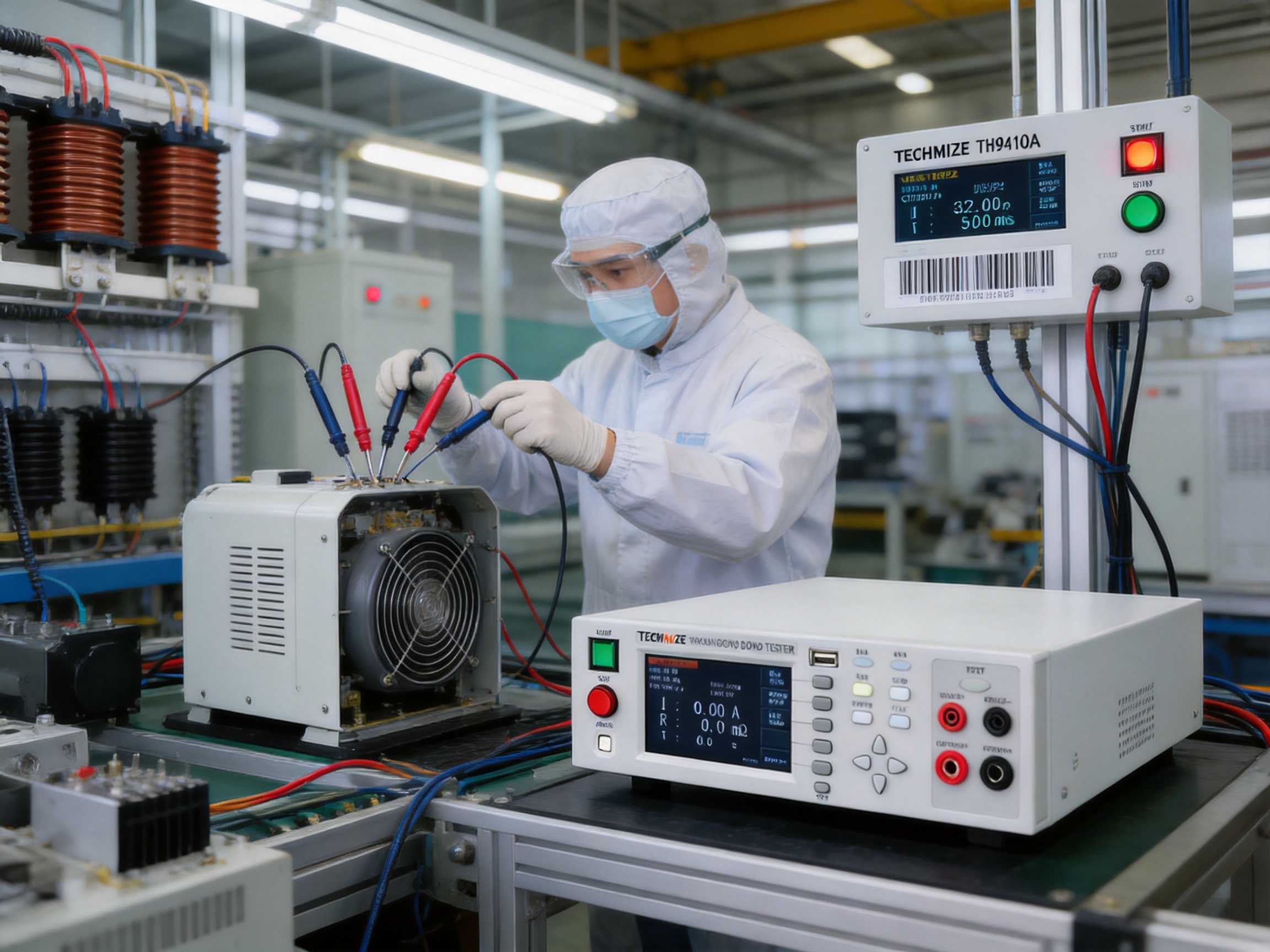
Modern manufacturing often combines electrical safety instruments with fixtures, barcode readers, programmable logic controllers, robotic handlers, and manufacturing execution systems. The TH9410A Series is designed with integration in mind. Front and rear panel output holes make it easier to install the unit within a test chassis or automated station.
When integrated into a larger system, the tester can form one stage of a comprehensive sequence. A product may be positioned by a fixture, identified by a barcode, tested for ground bond resistance, evaluated against programmed limits, and then released or diverted based on the result. The exact control architecture depends on the system designer, but the instrument’s physical connection options support this type of deployment.
Technical Specification Summary
| Specification | TH9410A | TH9411A |
| Test current range | 1.00 A to 45.00 A | 1.00 A to 32.00 A |
| Current setting resolution | 0.01 A | 0.01 A |
| Current readback resolution | 0.01 A | 0.01 A |
| Current accuracy | Plus or minus 2 percent of reading plus 3 digits | Plus or minus 2 percent of reading plus 3 digits |
| Resistance test range | 0 to 600 milliohms, subject to the specified current relationship | 0 to 600 milliohms, subject to the specified current relationship |
| Resistance accuracy | Plus or minus 2 percent of reading plus 2 digits | Plus or minus 2 percent of reading plus 2 digits |
| Resistance resolution | 1 milliohm or 0.1 milliohm according to range | 1 milliohm or 0.1 milliohm according to range |
| Upper resistance limit setting | 0 to 600 milliohms | 0 to 600 milliohms |
| Lower resistance limit setting | 0 to 600 milliohms, below the upper limit | 0 to 600 milliohms, below the upper limit |
| Test-time range | 0 or 0.5 to 999.9 seconds | 0 or 0.5 to 999.9 seconds |
| Test-time resolution | 0.1 second | 0.1 second |
| Test-time accuracy | Plus or minus 0.1 percent plus 0.05 second | Plus or minus 0.1 percent plus 0.05 second |
| Display | 480 by 272 dot backlit TFT-LCD | 480 by 272 dot backlit TFT-LCD |
| Data storage | Up to 20 test files, each with up to 20 test steps | Up to 20 test files, each with up to 20 test steps |
| Input voltage | 110 V or 220 V | 110 V or 220 V |
| Input frequency | 47.5 Hz to 63 Hz | 47.5 Hz to 63 Hz |
| Power consumption | Up to 900 VA | Up to 800 VA |
The specification table should be read together with the complete operating manual and the requirements of the relevant safety standard. In particular, the maximum resistance range is related to the selected test current. Users should confirm the permitted combination of current, resistance, fixture, and test duration before creating a production procedure.
Manufacturing and Engineering Strengths
The product is supplied by JIANGSU BAISHENG INDUSTRIAL CO., LTD., a technology-driven manufacturer and supplier of laboratory equipment and electrical safety testing instruments. Established in 2010, the company combines product research and development with international trade experience. Its stated focus is the development of high-end laboratory equipment and safety compliance instruments for domestic and overseas users.
The company’s development history reflects a gradual expansion from technical engineering into organized product manufacturing and international supply. Its predecessor was a research and development studio specializing in electronic testing. The founding team included engineers with backgrounds in laboratory equipment and safety compliance testing. This origin is significant because the company’s product direction is connected to practical measurement problems rather than being limited to general-purpose distribution.
After developing its first independently produced equipment line, the company expanded investment in research and development and adopted a technology-plus-trade strategy. This combination can be valuable to international customers because technical design, manufacturing coordination, documentation, export communication, and application support are considered together.
Research-Led Product Development
A dedicated research and development team supports the design of instruments such as the TH9410A Series. Ground bond testing requires coordination among power electronics, measurement circuitry, thermal management, display systems, embedded controls, safety interlocks, and mechanical construction. A product cannot achieve dependable results through an isolated focus on only one of these areas.
The independent power amplifier, four-terminal architecture, programmable test controls, display interface, and stored test procedures illustrate the need for multidisciplinary engineering. These functions must work together without allowing high-current output to compromise measurement stability or operator safety. A research-led development process helps address these interactions during design, verification, and production preparation.
Precision-Oriented Manufacturing
Precision laboratory equipment depends on controlled component selection, careful assembly, inspection, calibration, and functional verification. In a ground bond tester, current-output performance and resistance-measurement accuracy are especially important. Manufacturing teams must ensure that high-current paths, sensing paths, connectors, circuit boards, and protective structures are assembled consistently.
The company emphasizes precise design and rigorous technical specifications. This orientation supports a manufacturing approach in which the instrument is evaluated as a complete measurement system rather than as a collection of unrelated parts. Output stability, display operation, test timing, limit judgment, data storage, keyboard lock, and safety lock functions all contribute to the practical quality of the finished tester.
Quality Management and Technical Compliance
According to the company information, its quality management system was further improved in 2022, and its products underwent rigorous technical specification certification. For customers purchasing laboratory and safety test equipment, a structured quality approach is important because instruments are often used to support compliance decisions and production release activities.
Quality management should include controlled documentation, inspection records, calibration practices, component traceability, production testing, and corrective-action procedures. The exact scope of these activities should be confirmed during technical discussions and purchasing evaluation. Nevertheless, the company’s emphasis on quality-system development indicates an intention to support consistent product performance as its markets expand.
Customization Capability
Laboratory and production customers do not always require identical configurations. Some need a stand-alone bench instrument, while others need a rack-mounted unit, a fixture-ready tester, a customized test sequence, or a solution that fits a particular production line. The TH9410A Series already includes features that support flexible deployment, including front and rear output access and programmable test files.
The manufacturer’s engineering background can also support discussions involving current ranges, test fixtures, application-specific limits, documentation, and integration requirements. Customization should be based on a clear technical specification and verified through sample testing. When handled systematically, customization can improve the match between the tester and the customer’s actual process instead of forcing the customer to redesign the entire workstation around a generic instrument.
International Supply and Customer Support
International trade experience is another stated strength of the company. Overseas customers often require more than a product shipment. They may need clear technical documentation, packaging coordination, export communication, application consultation, spare-parts planning, and assistance with installation or training.
A supplier that understands both engineering and international business can help reduce communication gaps. Technical requirements can be translated into defined specifications, while commercial and logistics requirements can be coordinated with the manufacturing schedule. For industrial buyers, this integrated approach can simplify procurement and support long-term cooperation.
Comparison with Basic or Less Specialized Test Equipment
The TH9410A should be evaluated against the requirements of the intended test rather than simply compared by purchase price. A handheld multimeter may measure resistance, but it usually does not provide the high-current output, four-terminal configuration, programmable limits, safety lock, extended test timing, or production-oriented data storage required for a controlled ground bond process.
A basic continuity tester may confirm that a connection is not completely open. It may not reveal whether the resistance is within a demanding limit under a specified current. Continuity and ground bond testing therefore serve different purposes. Continuity is generally a preliminary electrical check, while ground bond testing provides a more controlled evaluation of protective conductor performance.
Some fixed-current testers may be suitable for one product type but less convenient when a factory produces multiple product families. The adjustable current range of the TH9410A provides greater flexibility. Similarly, instruments without four-terminal measurement may produce readings that include a larger contribution from cables and contact points, especially when measuring low-resistance paths.
Another distinction is the ability to support standardized workflows. Test-file storage, keyboard locking, safety locking, long test-time capability, and front-and-rear connection options are practical features for organizations that need repeatability, operator control, and future automation. These features may have less importance in occasional service work but become increasingly valuable as production volume and product variety increase.
Recommended Implementation Practices
Define the Test Objective
Before using the tester, the engineering team should identify exactly which grounding path is being evaluated. The test points should represent the protective conductor path from the relevant accessible conductive part to the grounding terminal or designated connection. The selected points, current, resistance limits, and duration should be documented in the work instruction.
Choose Suitable Fixtures
Fixtures should provide secure, repeatable, and low-resistance contact. Probe pressure, contact material, cable routing, mechanical stability, and operator accessibility all affect the quality of the measurement. Four-terminal measurement reduces the influence of lead resistance but does not eliminate errors caused by poor contact, contamination, loose clips, or incorrect placement.
Set Appropriate Limits
The upper and lower resistance limits should be based on the product design, applicable standard, risk assessment, and validation data. Limits should not be selected only because they are convenient or because they produce a desired pass rate. A properly established limit should distinguish acceptable grounding performance from a condition that requires investigation.
Control the Test Environment
Temperature, humidity, contamination, mechanical movement, and electromagnetic interference can influence electrical measurements. Production stations should be arranged to prevent test leads from contacting high-voltage wiring or moving machinery. Operators should receive training in the hazards associated with high-current testing and should follow the equipment’s safety instructions.
Verify the Instrument
The tester should be inspected and calibrated according to the facility’s quality system and the manufacturer’s recommendations. Verification may include checking current output, resistance measurement, display behavior, timing, limit judgment, and safety functions. Calibration intervals should reflect usage frequency, environmental conditions, internal quality requirements, and applicable compliance obligations.
Maintain Records
Test records help organizations identify trends and demonstrate that inspections were performed. Depending on the production system, records may include the product serial number, test-file identifier, current setting, measured resistance, test duration, pass or fail status, operator, workstation, and date. The instrument’s internal storage supports local procedure management, while broader record retention may require external systems.
How the Instrument Supports Continuous Improvement
Ground bond data can reveal more than individual failures. When collected over time, it can show whether a process is becoming unstable. A gradual rise in resistance may indicate tool wear, deteriorating contact surfaces, supplier variation, incorrect torque, or changes in plating and coating. A sudden increase may point to a new assembly method, component substitution, fixture damage, or an operator instruction problem.
Engineers can use this information to establish baseline values and variation limits. Products that consistently pass near the upper resistance threshold may deserve additional review even if they remain technically acceptable. This type of preventive analysis can reduce field risk and help improve the durability of the grounding system.
The tester also supports design comparison. During development, engineers can evaluate different conductor sizes, fastening methods, bonding straps, coatings, welds, and grounding terminals. By using controlled current and a repeatable measurement method, design teams can compare alternatives with greater confidence than through visual examination alone.
Responsible Use and Technical Boundaries
A ground bond tester is a specialized instrument and must be used by trained personnel. High-current output can create heat, sparks, or hazardous touch conditions if connections are incorrect or if the device under test is not prepared properly. Operators should follow the manufacturer’s instructions, use appropriate personal protective measures, and ensure that test fixtures are mechanically secure.
Ground bond testing is only one part of a complete electrical safety program. Depending on the product, additional tests may include protective conductor continuity, insulation resistance, dielectric withstand, leakage current, functional operation, polarity, and visual inspection. The test sequence should be developed by qualified safety and compliance engineers.
Users should also distinguish between the instrument’s specified capabilities and the requirements of a particular regulation or standard. The TH9410A provides adjustable current, resistance measurement, limit setting, and timing functions, but the correct test parameters must be determined for each product. The instrument should not be treated as a substitute for an engineering risk assessment or formal compliance review.
Why the TH9410A Series Is a Practical Long-Term Choice
The value of a safety tester is measured not only by its initial measurement range but also by its ability to remain useful as products, processes, and production volumes change. The TH9410A Series is positioned for long-term use because it combines a broad current range with configurable resistance limits, extended test timing, stored procedures, operator controls, and flexible physical connections.
For a laboratory, this combination enables detailed investigation and repeatable verification. For a production line, it supports standardized testing and future automation. For a manufacturer with multiple product categories, the adjustable settings reduce the need to purchase separate instruments for every application. For a quality department, the four-terminal architecture and stable current output provide a stronger basis for trustworthy low-resistance results.
The product is also supported by a supplier whose stated strengths include research and development, precision engineering, manufacturing experience, quality-system improvement, customization, and international trade. These capabilities are relevant when the customer requires more than a standard catalog purchase and needs assistance with application matching, test fixtures, documentation, or production integration.
By combining measurement performance with operational control, the tester helps organizations move from simple pass-or-fail continuity checks toward a more structured ground bond verification process. That transition can improve product safety, reduce process variation, support compliance activities, and provide useful information for continuous manufacturing improvement.
Q&A
What is a ground bond test?
A ground bond test applies a controlled electrical current through a product’s protective grounding path and measures the resulting resistance. It verifies that exposed conductive parts are connected to the protective earth terminal through a sufficiently low-resistance path.
What is the maximum current of the TH9410A?
The TH9410A supports an adjustable test current from 1.00 A to 45.00 A. The related TH9411A model supports 1.00 A to 32.00 A.
Why is four-terminal testing important?
Four-terminal testing separates the current-carrying leads from the voltage-sensing leads. This reduces the influence of test-lead and contact resistance and improves the reliability of low-resistance measurements.
What resistance range can the instrument measure?
The stated resistance range is zero to 600 milliohms. The usable maximum depends on the selected test current, with the specification defined by the relationship Rmax less than or equal to 6 divided by the set current. When the current is below 10 A, the maximum resistance can reach 600 milliohms.
Can the resistance limits be programmed?
Yes. The instrument provides upper and lower resistance limit settings. The upper limit can be set from zero to 600 milliohms, and the lower limit can be set within the available range below the upper limit.
How long can a test run?
The test-time range is 0.5 to 999.9 seconds. A setting of zero enables continuous operation. The time resolution is 0.1 second.
Is the tester suitable for automated production systems?
Yes. Front and rear panel output holes facilitate installation in test fixtures, standard test chassis, and automated testing environments. Stored test files and keyboard and safety lock functions also support controlled production operation.
How many test procedures can be stored?
The instrument can store up to 20 test files, and each file can contain up to 20 test steps. This allows users to organize procedures for multiple products or test sequences.
What industries can use the TH9410A Series?
Applications include household appliances, transformers, motors, electric heating equipment, lighting products, new energy vehicles, electronic components, medical equipment, laboratory projects, and automated production testing.
Does ground bond testing replace insulation or dielectric testing?
No. Ground bond testing evaluates the integrity of the protective grounding path. Insulation resistance, dielectric withstand, leakage current, and other tests evaluate different safety characteristics. A complete safety program may require several test methods.
What display does the instrument use?
The tester uses a 480 by 272 dot backlit TFT-LCD. The display is designed to provide clear visibility of settings, readings, test status, and judgment information.
What input power options are available?
The stated input voltage options are 110 V and 220 V, with an input frequency range of 47.5 Hz to 63 Hz. Users should confirm the correct configuration when ordering and installing the equipment.
What should be considered when selecting test limits?
Limits should be based on the product design, applicable safety requirements, selected test current, test points, fixture configuration, and validated engineering data. Limits should be reviewed by qualified personnel rather than chosen solely for convenience.
What is the manufacturer’s main strength?
JIANGSU BAISHENG INDUSTRIAL CO., LTD. combines research and development, precision laboratory equipment manufacturing, electrical safety testing expertise, quality-system development, customization capability, and international trade experience. These strengths support both standard product supply and application-specific cooperation.
Conclusion
The TH9410A Series Backlit LCD Display Ground Bond Tester provides a comprehensive solution for verifying protective grounding paths in laboratory, service, quality-control, and production environments. Its adjustable current range, low-resistance measurement capability, four-terminal test mode, independent power amplifier circuit, programmable timing, data storage, safety controls, and automated-system connection options address the practical requirements of modern electrical safety testing.
The principal TH9410A model reaches 45.00 A, while the TH9411A extends to 32.00 A. Both models are designed around the need for controlled output, accurate measurement, repeatable procedures, and clear operation. These characteristics make the series more versatile than basic continuity instruments and more adaptable than fixed-purpose testers.
Supported by a company with an engineering-led history, research and development resources, manufacturing experience, quality-system investment, and international supply capabilities, the product can serve as part of a broader safety and quality infrastructure. When correctly configured and used with suitable fixtures, calibration practices, engineering limits, and operator training, the tester can help manufacturers identify grounding defects early, improve process consistency, and strengthen confidence in the electrical safety of finished products.
References
1. General principles of electrical safety testing and protective conductor verification.
2. Measurement practice for low-resistance electrical connections using four-terminal methods.
3. Principles of Ohm’s law and voltage-drop measurement in controlled-current resistance testing.
4. Quality management practices for laboratory and production measurement equipment.
5. Product technical specifications for the TH9410A and TH9411A Ground Bond Tester Series.
6. Engineering guidance for electrical safety evaluation of household appliances, industrial equipment, electronic assemblies, medical devices, and new energy vehicle components.
7. Manufacturer-provided application information, operating features, and company development profile.
Product: TH9410A Series Backlit LCD Display Ground Bond Tester
PREV:UTH-150-A High-Low Temperature Humidity Cycling Chamber: Precision Environmental Simulation for Reliable Product Testing
NEXT:High-Precision Vacuum Cryogenic Sample Transfer Chambers for Reliable Laboratory Workflows
NEXT:High-Precision Vacuum Cryogenic Sample Transfer Chambers for Reliable Laboratory Workflows
Interested in cooperation or have questions?
Featured Products
Related products
Quick Link
Contact Information
- Tel: +86-13861043568
- E-mail: 1840784112@qq.com
- Add: Tianting District, Changzhou City, Jiangsu Province, China, No. 6 Hecircuit
Scan Code
Copyright © JIANGSU BAISHENG INDUSTRIAL CO., LTD.
All Rights Reserved. Privacy Custom Precision Laboratory Testing Equipment Manufacturers
