 English
 Español

NEWS
NEWS
NEWS
NEWS
NEWS
NEWS
NEWS
NEWS
NEWS
NEWS
NEWS
NEWS
NEWS
NEWS
NEWS
NEWS

Peng Shulan — Regional Sales Consultant
Home / Author / Peng Shulan — Regional Sales Consultant / High-Precision AC/DC Hipot and Insulation Resistance Testing for Safer Electrical Products
High-Precision AC/DC Hipot and Insulation Resistance Testing for Safer Electrical Products
Content
- 1 Why Electrical Safety Testing Requires a Specialized Instrument
- 2 Overview of the TH9120 Series
- 3 Key Technical Advantages
- 4 AC Withstand Voltage Testing
- 5 DC Withstand Voltage Testing
- 6 Arc Detection and Open- or Short-Circuit Evaluation
- 7 Programmable Testing and Production Automation
- 8 Safety Protection Features
- 9 Touchscreen Operation and Data Recording
- 10 Applications Across Multiple Industries
- 11 Comparison with Conventional Testing Approaches
- 12 Technical Specification Summary
- 13 Manufacturing Strength and Engineering Capability
- 14 Recommended Implementation Practices
- 15 Calibration, Maintenance, and Traceability
- 16 How the Tester Supports Better Quality Management
- 17 Selection Guidance for Buyers
- 18 Frequently Asked Questions
- 18.1 What is the primary purpose of the TH9120 Series?
- 18.2 What is the highest AC test voltage?
- 18.3 What is the highest DC test voltage?
- 18.4 What is the insulation resistance measurement range?
- 18.5 Can the instrument test electric vehicle battery systems?
- 18.6 Does the tester automatically discharge a product after a DC test?
- 18.7 How many test programs can be stored?
- 18.8 Can the tester be integrated into an automated production line?
- 18.9 What is the difference between withstand voltage testing and insulation resistance testing?
- 18.10 Why is a waiting time useful in DC testing?
- 18.11 Does the tester require a special operating environment?
- 18.12 How does the touchscreen improve operation?
- 18.13 What safety measures should be used with a high-voltage tester?
- 19 Conclusion
- 20 References
- 21 Product: TH9120 Series AC/DC Withstanding Voltage & Insulation Resistance Hipot Tester
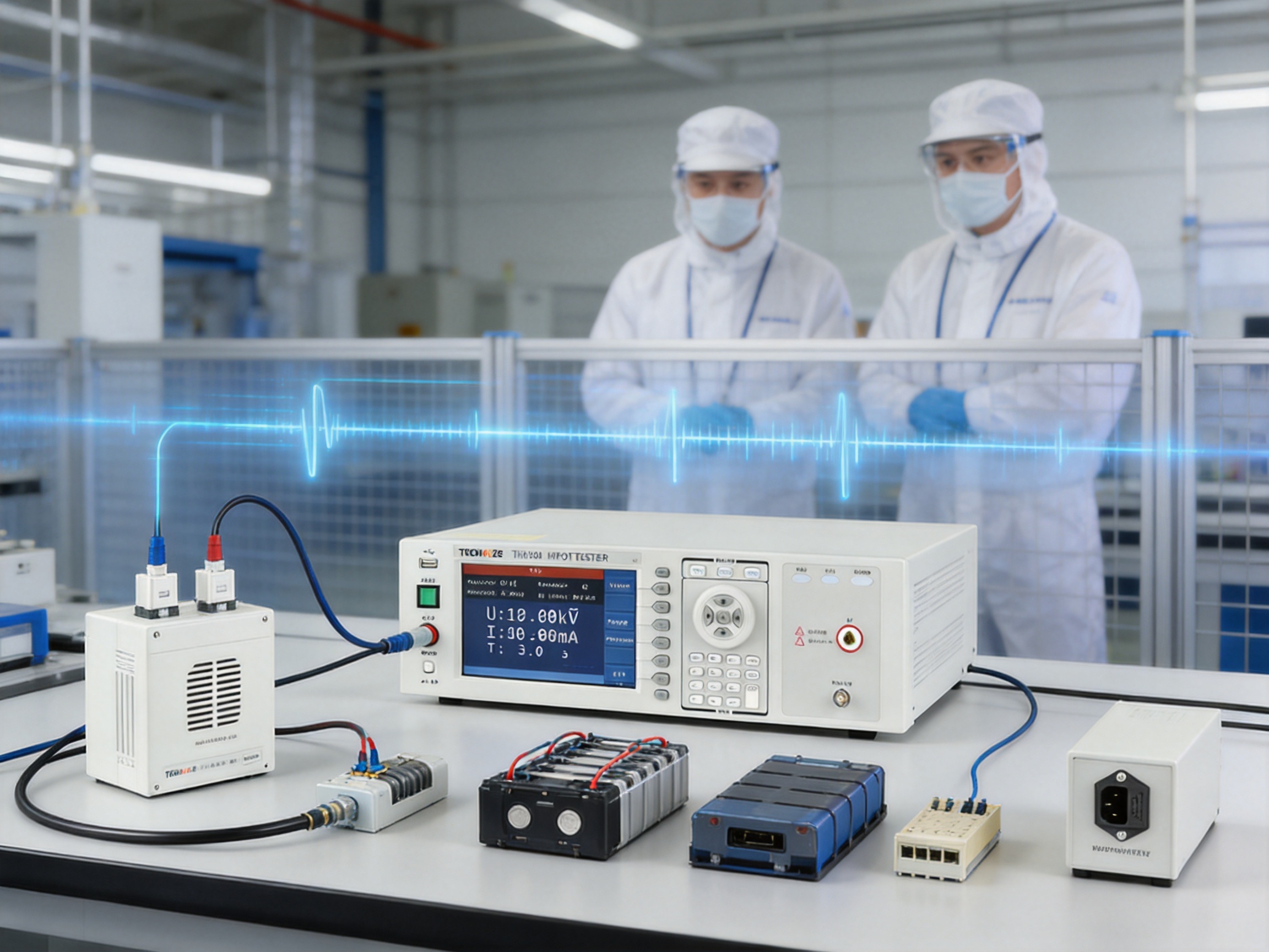
Electrical safety testing is a critical stage in the design, production, inspection, and certification of modern electrical and electronic products. As products become more compact, more powerful, and more interconnected, the quality of their insulation systems has a direct effect on user safety, equipment reliability, and regulatory compliance. A single weakness in insulation can create leakage current, electrical arcing, flashover, premature component failure, or a dangerous shock hazard.
The TH9120 Series AC/DC Withstanding Voltage and Insulation Resistance Hipot Tester is designed to address these challenges with a combination of high-voltage output, sensitive current measurement, insulation resistance testing, programmable sequences, safety protection, data storage, and communication interfaces. It is suitable for manufacturers, laboratories, quality-control departments, repair centers, research institutions, and automated production lines that require repeatable and traceable electrical safety testing.
The instrument combines several functions in one platform. Depending on the selected model, users can perform AC withstand voltage testing, DC withstand voltage testing, insulation resistance measurement, arc detection, and open- or short-circuit detection. This multi-purpose design reduces the need for several separate instruments and provides a more consistent testing process across different product categories.
Why Electrical Safety Testing Requires a Specialized Instrument
Electrical insulation is expected to separate hazardous voltage from accessible conductive surfaces, signal circuits, grounded structures, and other parts that must remain safe during normal use. However, insulation can be affected by material defects, contamination, moisture, mechanical damage, manufacturing variation, thermal stress, aging, or incorrect assembly.
A visual inspection alone cannot identify many of these problems. A component may appear undamaged while containing microscopic cracks, insufficient creepage distance, weak bonding, or an internal defect that becomes dangerous only when a high voltage is applied. Electrical safety testing introduces controlled electrical stress and measures the response of the product under test.
Withstanding voltage testing, often called hipot testing, evaluates whether insulation can withstand a voltage substantially higher than its normal operating voltage for a specified time. The purpose is to identify breakdown, excessive leakage current, flashover, or other abnormal behavior.
Insulation resistance testing applies a controlled DC voltage and measures the resistance between isolated conductors or between a conductor and a protective earth connection. A high resistance generally indicates effective insulation, while a lower value may indicate contamination, moisture, material deterioration, or an assembly defect.
Arc detection is also important because an insulation system may produce intermittent or unstable discharges before a complete breakdown occurs. Detecting abnormal current behavior can help manufacturers identify weak products that might pass a simple voltage test but fail during long-term operation.
The TH9120 Series is designed to bring these testing methods together in a controlled, programmable, and safety-oriented system. This approach is particularly valuable where products must be tested repeatedly under consistent production conditions.
Overview of the TH9120 Series
The TH9120 Series is a high-voltage electrical safety tester developed for AC and DC withstand voltage testing and insulation resistance measurement. The series is available in different configurations so that users can select a model according to the required test modes.
The TH9120 model supports AC, DC, insulation resistance, and open- or short-circuit detection functions. The TH9120A is configured for AC testing and open- or short-circuit detection. The TH9120D is configured for DC withstand voltage and insulation resistance testing. This model structure allows customers to choose a practical combination of functions instead of purchasing a fully equipped system when only selected test modes are required.
The AC withstand voltage range extends from 0.05 kV to 10.0 kV. The DC withstand voltage range extends from 0.05 kV to 12.0 kV. These ranges allow the tester to serve low-voltage electrical assemblies as well as high-voltage insulating components and specialized products.
The AC output is rated at up to 200 VA, corresponding to 10.0 kV and 20 mA. The DC output is rated at up to 120 VA, corresponding to 12.0 kV and 10 mA. These output capabilities provide sufficient test energy for a broad range of products while retaining controlled measurement and protection functions.
For insulation resistance testing, the instrument provides a DC output range of 0.05 kV to 12.0 kV and a resistance measurement range from 0.1 MΩ to 50.0 GΩ. This wide resistance range makes the instrument suitable for both conventional insulation checks and high-resistance measurements on advanced insulating materials.
Key Technical Advantages
Multi-Mode Testing in One Instrument
One of the main advantages of the TH9120 Series is its integration of multiple electrical safety functions. A production department may need to perform an AC withstand test on one product, a DC withstand test on another product, and an insulation resistance test on a third product. Using independent instruments for each task can increase cost, occupy more bench space, and create differences in operating procedures.
The multi-mode architecture of the TH9120 Series simplifies this process. The tester can support AC withstand voltage, DC withstand voltage, insulation resistance, and open- or short-circuit detection according to the model configuration. This arrangement provides a consistent user interface and helps standardize test methods across different production lines and laboratory workstations.
Integrated testing also reduces the chance of incorrect instrument selection. When test procedures are stored in the system, operators can select the relevant product program rather than manually entering every parameter for every test. This is particularly useful in facilities that manufacture several product families with different voltage, current, time, and pass-fail requirements.
High-Voltage Output for Demanding Applications
The tester provides AC output up to 10.0 kV and DC output up to 12.0 kV. These levels are suitable for a broad selection of electrical and electronic safety applications, including high-voltage relays, optocouplers, switches, cables, battery modules, household appliances, lighting products, and insulating materials.
The voltage resolution is 2 V. Fine voltage adjustment allows the operator to establish a suitable stress level without relying on coarse increments. This is valuable when a test specification requires a specific voltage or when the user needs to gradually increase stress during research and development work.
The stated voltage accuracy is ±(1% of the setting value + 0.1% of full scale) for withstand voltage testing. This specification supports reliable comparison between test results and documented product requirements. Accurate voltage control is also important when testing products with narrow safety margins, because excessive test voltage can create unnecessary stress while insufficient voltage may fail to reveal an insulation weakness.
Current Measurement for Sensitive Failure Detection
Leakage current is an essential parameter in withstand voltage testing. The TH9120 Series provides an AC current range from 0.001 mA to 20 mA and a DC current range from 0.0001 mA to 10 mA, depending on the model configuration.
For DC testing, the resolution can reach 0.1 µA. This sensitivity enables the instrument to detect small current changes that may indicate contamination, insulation deterioration, an assembly error, or an early-stage breakdown process.
The current accuracy specification is ±(1% of reading + 0.5% of full scale) for the relevant DC range. For AC testing, the accuracy varies according to current level. Between 0.100 mA and 2.999 mA, the specified accuracy is ±(1% of reading + 0.5% of full scale). Between 3.00 mA and 20.00 mA, it is ±(1.5% of reading + 0.5% of full scale).
These measurement capabilities help manufacturers establish reliable pass-fail limits. The instrument can also identify products that exhibit unstable leakage behavior instead of simply recording whether a final breakdown occurred.
Insulation Resistance Measurement up to 50.0 GΩ
Insulation resistance testing is often used as a complementary test to withstand voltage testing. While withstand testing evaluates the ability of insulation to tolerate a defined high-voltage stress, insulation resistance testing quantifies the resistance of the insulating path.
The TH9120 Series covers a resistance range from 0.1 MΩ to 50.0 GΩ. This range supports measurements on cables, insulating films, molded components, electrical assemblies, battery systems, and other products where resistance may range from moderately high to extremely high.
The instrument supports DC test voltages from 0.05 kV to 12.0 kV for insulation resistance measurement. The voltage resolution is 2 V, and the voltage accuracy is specified as ±(1% of the setting value + 0.5% of full scale).
Resistance measurement accuracy depends on test voltage and resistance range. At test voltages of 5.0 kV or higher, the specified accuracy is ±(3% of reading + 0.1% of full scale) from 1 MΩ to 1 GΩ, ±(3% of reading + 0.1% of full scale) from 1 GΩ to 10 GΩ for the applicable configuration, and ±(10% of reading + 1% of full scale) from 10 GΩ to 50 GΩ. At test voltages below 500 V, the specified range from 0.1 MΩ to 1 GΩ is ±(5% of reading + 2% of full scale).
Because high-resistance measurement can be influenced by humidity, surface contamination, test lead condition, and environmental interference, the tester includes specifications that help users evaluate results appropriately. For best accuracy, testing should be performed in a controlled environment and with clean, correctly connected test fixtures.
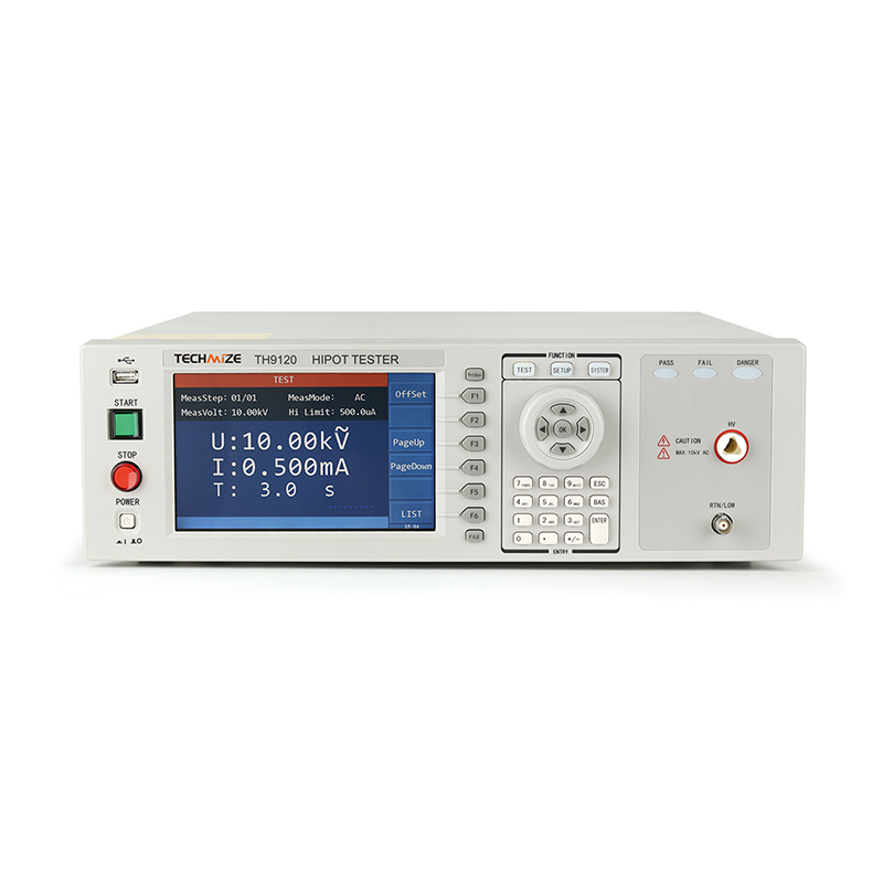
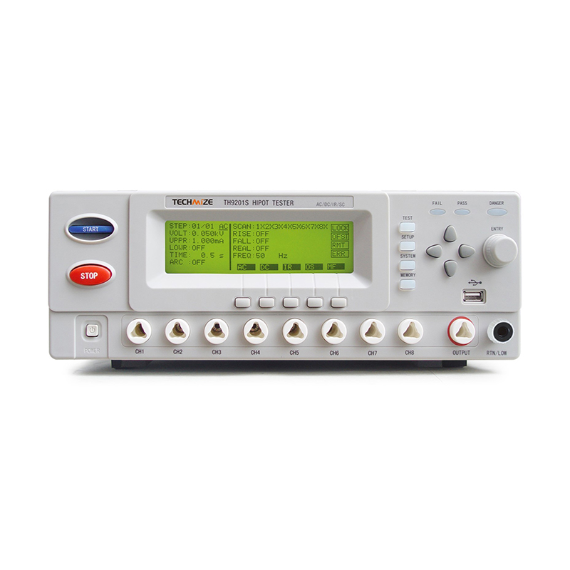
TH9120 Series AC/DC Withstanding Voltage & Insulation Resistance Hipot Tester
AC Withstand Voltage Testing
AC withstand testing is commonly used for products that operate from an AC power supply or that must meet established dielectric strength requirements. The TH9120 Series produces a 50 Hz or 60 Hz sine wave with a frequency accuracy of ±0.1%. This controlled waveform helps maintain consistent test conditions.
AC testing applies alternating electrical stress to the insulation system. It can reveal breakdown, flashover, abnormal leakage, and other defects that may not be visible during ordinary functional testing. Since the voltage polarity alternates continuously, AC testing can provide a demanding evaluation of insulation interfaces and material boundaries.
The AC output capability reaches 10.0 kV, with output power up to 200 VA at 10.0 kV and 20 mA. The maximum short-circuit current for AC testing is specified as 40 mA. This provides the necessary output capability for demanding tests while maintaining controlled current monitoring.
AC withstand testing is widely used for household appliances, audio-visual equipment, information technology products, lighting equipment, electric heating appliances, power supplies, motors, transformers, and industrial electrical assemblies. It is also useful for checking high-voltage relays, switches, optocouplers, and other components that must maintain isolation between circuits.
DC Withstand Voltage Testing
DC withstand testing is useful when a product specification calls for a direct high-voltage stress or when the test setup requires a lower charging current after the product under test has reached the applied voltage. The TH9120 Series provides DC output up to 12.0 kV, with output power up to 120 VA at 12.0 kV and 10 mA.
Because the product under test may retain an electrical charge after a DC test, automatic discharge is an important safety function. The TH9120 Series includes automatic discharge after DC withstand testing. This feature helps reduce residual voltage before the operator or an automated system handles the product.
DC testing is particularly relevant to battery modules, electric vehicle electrical systems, high-voltage cables, capacitive components, insulation systems, and products that include rectification or power-conversion circuits. It can also be used when a testing standard specifies DC dielectric stress rather than AC stress.
The instrument includes waiting-time control for DC withstand voltage testing. This allows the operator to define a stabilization period before the main test timing begins. Such a function can be useful when the product under test has significant capacitance or when the test procedure requires the voltage to settle before evaluating leakage current.
Arc Detection and Open- or Short-Circuit Evaluation
Some insulation defects produce intermittent electrical discharges rather than an immediate hard breakdown. These discharges can be associated with sharp edges, voids, air gaps, damaged insulation, contamination, or incorrect assembly. If a test system evaluates only the final current level, intermittent arcing may not be adequately identified.
The TH9120 Series includes arc detection functions for suitable test configurations. Arc detection settings can be programmed in AC and DC modes. The specified AC setting range is 1.0 mA to 20.0 mA, while the DC setting range is 1.0 mA to 10.0 mA.
The open- and short-circuit detection function is designed for test arrangements that use a sampling capacitance. The sampling capacitance range is 0.001 nF to 40 nF. The open-circuit judgment range is 10% to 100%, and the short-circuit judgment range is 100% to 500%.
These functions can help identify fixture connection errors, missing components, incorrect wiring, and abnormal product conditions before the main test proceeds. In a production environment, this can reduce false results and prevent a defective connection from being mistaken for a product failure.
Programmable Testing and Production Automation
Modern quality systems require more than a one-time manual measurement. They require repeatability, traceability, process control, and the ability to connect test results to production records. The TH9120 Series supports these requirements through internal program storage and external communication interfaces.
The internal memory can store up to 100 files, with up to 50 editable steps in each file. A file may represent a product model, customer specification, production station, or test standard. Multiple steps can be arranged to perform a complete sequence, such as open-circuit verification, AC withstand testing, DC withstand testing, insulation resistance measurement, discharge, and final judgment.
Multi-step programming reduces manual intervention and improves consistency between operators. It also helps prevent common setup errors, such as entering the wrong test voltage, applying an incorrect test duration, omitting a discharge period, or using an unsuitable current limit.
The tester includes RS232, USB device, USB host, LAN, and handler interfaces as standard interfaces. GPIB is available as an optional interface. These connections allow the instrument to communicate with computers, programmable logic controllers, automatic handlers, scanners, data systems, and other production equipment.
In an automated line, the tester can receive a product identification code, recall the correct test program, initiate a test after receiving a safety confirmation, return the pass or fail result, and send measurement data to a manufacturing execution or quality management system. The exact automation architecture depends on the customer’s equipment and software, but the available interfaces provide a strong foundation for integration.
Typical Automated Test Sequence
A typical automated process may begin with a barcode reader identifying the product. The control system then selects the correct stored file. The handler confirms that the product is correctly positioned, and the interlock circuit verifies that the high-voltage enclosure or fixture is closed.
The tester may first perform an open- or short-circuit check. If the connection is acceptable, the system applies the programmed voltage using the defined rise time. The test then continues for the selected duration while monitoring leakage current and arc behavior. For DC testing, a waiting period may be used before the main judgment is made.
After the withstand test, the instrument can perform an insulation resistance test if required. The product is then automatically discharged after the DC test. Finally, the tester provides a pass or fail signal through the handler interface, while measurement results can be transmitted through a communication port for storage and analysis.
Safety Protection Features
High-voltage testing must be conducted with strict attention to operator protection. The TH9120 Series incorporates several safety functions intended to reduce the risk of accidental contact, incorrect startup, and unauthorized operation.
Shock Protection
The shock protection function is specified at 0.5 mA ± 0.25 mA and can be selected on or off according to the application. This function is intended to help identify an abnormal human-contact or leakage condition during testing. It should be used together with appropriate guarding, grounding, interlocks, warning signs, personal protective equipment, and documented safe operating procedures.
Start Protection and Interlock
The start protection function uses an interlock connection. High-voltage output is permitted when the specified pin is connected with the low terminal. This allows the tester to be connected to a safety enclosure, fixture, door switch, or external control circuit.
An interlock should be designed so that opening the guarded area prevents the high-voltage test from starting or interrupts the test according to the equipment safety design. This is especially important in automated systems where the operator may not directly control the start of every cycle.
Panel Operation Protection
Panel operation protection includes key locking and password functions. These controls help prevent unauthorized modification of stored programs or test limits. In production environments, restricted access can improve process discipline and protect validated test parameters.
Pass and Fail Indication
The instrument provides clear result indications. A pass condition is shown by a short sound and green light, while a fail condition is shown by a long sound and red light. Clear visual and audible signals help operators identify results quickly, especially in environments where multiple test stations are operating simultaneously.
Touchscreen Operation and Data Recording
The TH9120 Series features a 7-inch high-resolution touchscreen. A touchscreen interface can simplify configuration of high-voltage tests because parameters such as voltage, current limit, rise time, fall time, waiting time, test duration, resistance limits, and arc thresholds can be displayed in an organized format.
A large screen also improves visibility when the instrument is placed on a production bench or laboratory table. Operators can review the active test step, measured values, test status, and result without relying on a small segmented display.
The one-touch screenshot function provides a convenient way to record the displayed test information. This can be useful during research and development, troubleshooting, acceptance testing, training, and quality investigations. Screenshots may supplement formal data records by preserving the visible test status and measured values at a particular time.
Although screenshots are useful, they should not replace a controlled data-recording system where traceability is required. For regulated or high-volume manufacturing, measurement data should ideally be transferred through the communication interfaces and stored with product identification, operator information, program version, timestamp, and calibration status.
Applications Across Multiple Industries
Household Appliances
Household appliances often combine high-voltage power circuits, accessible metal surfaces, motors, heating elements, control boards, and protective earth connections. Withstand voltage and insulation resistance tests can help verify that the appliance maintains adequate separation between live parts and accessible surfaces.
Typical products include refrigerators, washing machines, microwave ovens, water heaters, air conditioners, electric ovens, hair dryers, vacuum cleaners, and kitchen appliances. The tester can be used during design verification, incoming inspection, production testing, and repair evaluation.
Information Technology and Audio-Visual Equipment
Computers, displays, printers, servers, audio systems, and communication equipment may contain multiple power domains and sensitive signal circuits. Safety testing confirms that the power input, chassis, shield, and internal circuits remain properly isolated.
The TH9120 Series can help manufacturers establish repeatable dielectric strength and insulation resistance procedures for power supplies, adapters, display assemblies, audio equipment, network devices, and other electronic products.
High-Voltage Components
High-voltage optocouplers, relays, switches, connectors, fuses, transformers, and insulating supports require reliable separation between circuits. The available voltage range and sensitive current measurement make the tester suitable for evaluating these components during development and production.
For component manufacturers, programmable testing can standardize procedures across batches. Test programs can be created for different part numbers, voltage ratings, construction types, or customer requirements.
Cables and Insulating Materials
Cables and insulating materials may be tested for dielectric strength and resistance between conductors, shields, or outer surfaces. The instrument can be applied to wires, cable assemblies, insulating films, molded materials, non-woven insulating fabrics, and other non-electrical products that must demonstrate electrical resistance.
Test fixtures should be selected carefully for the material geometry. Surface leakage, moisture, electrode shape, contact pressure, and environmental conditions can affect the measured result. Proper fixture design is therefore an important part of achieving meaningful measurements.
New Energy Vehicles and Battery Systems
Electric vehicles, hybrid vehicles, charging equipment, battery packs, and high-voltage auxiliary systems require robust electrical isolation. A failure in the insulation system can create a serious safety risk for service personnel, vehicle occupants, or connected equipment.
The TH9120 Series can support testing of battery modules, high-voltage cable assemblies, power electronics, charging components, motor systems, and other electrical assemblies. Depending on the product design and applicable standard, AC withstand, DC withstand, insulation resistance, and discharge tests may be included in the production sequence.
Because battery and vehicle systems can contain significant capacitance, the use of waiting time and automatic discharge is especially important. Test engineers should define appropriate procedures for charging, stabilization, measurement, and safe discharge based on the product’s electrical characteristics.
Research and Development Laboratories
In research and development, engineers often need to compare materials, evaluate prototypes, identify insulation weaknesses, and determine suitable production limits. The instrument’s broad voltage range, high resistance measurement capability, programmable time parameters, and screenshot function make it useful for laboratory investigations.
Development engineers can create controlled test sequences and use the stored programs to repeat measurements as a design evolves. The ability to set rise time and fall time is helpful when studying how a prototype responds to gradually applied or removed electrical stress.
Comparison with Conventional Testing Approaches
Many basic electrical safety test arrangements rely on separate instruments, manual switching, external timers, and handwritten records. Such arrangements may be adequate for occasional experiments, but they can become inefficient and inconsistent in a production environment.
Compared with a single-function tester, the TH9120 Series offers a wider range of integrated test modes. A user can select AC, DC, insulation resistance, or open- and short-circuit functions according to the model. This reduces the need to move products between separate workstations.
Compared with a manually operated high-voltage source, the TH9120 Series provides programmable rise time, fall time, waiting time, test duration, current limits, storage, result indication, and automatic discharge. These functions improve repeatability and help reduce dependence on operator timing and judgment.
Compared with a basic resistance meter, the instrument combines high-voltage insulation resistance measurement with withstand voltage testing and safety interlocks. This is valuable when a product specification requires both resistance and dielectric strength verification.
Compared with an isolated bench instrument that has no data interface, the TH9120 Series provides RS232, USB, LAN, handler, and optional GPIB connectivity. These interfaces support automation, data acquisition, and integration with production control systems.
Its 7-inch touchscreen, one-touch screenshot function, internal program storage, high-voltage output, and broad resistance range create a practical balance between laboratory capability and production usability.
Technical Specification Summary
| Item | Specification |
| Available models | TH9120, TH9120A, TH9120D |
| Test modes | AC, DC, insulation resistance, open- and short-circuit detection according to model |
| AC withstand voltage range | 0.05–10.0 kV |
| DC withstand voltage range | 0.05–12.0 kV |
| AC output power | 200 VA, 10.0 kV / 20 mA |
| DC output power | 120 VA, 12.0 kV / 10 mA |
| AC waveform | 50/60 Hz sine wave, ±0.1% |
| Voltage resolution | 2 V |
| AC current range | 0.001–20 mA |
| DC current range | 0.0001–10 mA |
| Maximum AC short-circuit current | 40 mA |
| Insulation resistance range | 0.1 MΩ–50.0 GΩ |
| Insulation resistance output | DC 0.05–12.0 kV |
| Test time | 0.3–999 seconds; zero indicates continuous testing |
| Rise time | 0.1–999 seconds; zero indicates off |
| Fall time | 0.1–999 seconds; zero indicates off |
| Waiting time | 0.1–999 seconds; applicable to DC withstand testing |
| Program storage | Up to 100 files and 50 steps per file |
| Standard interfaces | RS232, USB device, USB host, LAN, handler |
| Optional interface | GPIB |
| Display | 7-inch high-resolution touchscreen |
| Power supply | 100–240 VAC, 47–63 Hz |
| Power consumption | Less than 100 W at no load; 300 W at rated power |
| Dimensions | 430 mm W × 132 mm H × 500 mm D |
| Weight | 21 kg |
Manufacturing Strength and Engineering Capability
The performance of an electrical safety tester depends not only on its published specifications but also on the engineering discipline used to design, assemble, verify, and support the product. JIANGSU BAISHENG INDUSTRIAL CO., LTD. positions itself as a technology-driven manufacturer and supplier of laboratory equipment and safety testing instruments.
The company was founded in 2010 and has developed its capabilities through a combination of research and development, product engineering, production experience, and international trade expertise. Its stated focus is on high-end laboratory equipment, safety compliance testing, precision design, and customized solutions.
The company’s development history began with an electronic testing research and development studio in 2013. The founding team included engineers with technical backgrounds in laboratory equipment and safety compliance testing. In 2016, the organization developed an independent production line and launched laboratory equipment with independent intellectual property rights.
In 2019, the company adopted a technology-and-trade development strategy. This approach combined increased research and development investment with broader overseas market activity. In 2022, the company further developed its quality management system and pursued technical specification certifications. By 2025, the company was continuing to focus on product innovation, digitalization, and broader application scenarios.
Design and Development Process
A modern high-voltage tester requires coordinated design of power conversion, insulation structure, measurement circuits, control software, safety circuits, thermal management, and mechanical housing. The engineering process must account for high-voltage clearance, creepage distance, electromagnetic interference, transient response, measurement stability, and user protection.
The company’s dedicated research and development team supports product refinement and customized engineering. This is useful for customers that require special fixtures, communication protocols, production-line integration, modified test programs, or application-specific configurations.
Precision Assembly and Quality Control
Precision assembly is important because high-voltage output and low-current measurement must operate together reliably. Connections, insulation barriers, shielding, grounding, sensor circuits, and control wiring must be installed and inspected carefully.
A disciplined manufacturing process should include incoming material inspection, assembly checks, wiring verification, functional testing, high-voltage performance verification, measurement calibration, safety interlock checks, communication testing, and final inspection. These stages help ensure that the delivered equipment performs consistently under laboratory and production conditions.
Customization and Technical Support
Different industries use different test fixtures, product geometries, acceptance criteria, and automation platforms. A manufacturer with both technical and international trade experience can help customers define a practical solution rather than supplying a generic instrument without application support.
Customization may include test fixture adaptation, program development, external control integration, data communication, special voltage or current limits, production-line signaling, operator access control, and documentation support. Such services can be particularly valuable in new energy, automotive electronics, cable manufacturing, and high-volume appliance production.
Recommended Implementation Practices
The instrument should be installed in a clean, dry, stable environment with suitable ventilation and sufficient working space. The specified operating environment is 0°C to 45°C with relative humidity from 20% to 90%. For storage, the specified temperature range is -10°C to 55°C with humidity below 80%.
For parameter comparison, the recommended environment is 18°C to 28°C with humidity from 30% to 70% RH. Maintaining a controlled environment is especially important when comparing high-resistance measurements over time.
Before testing, operators should verify the power supply, protective earth connection, high-voltage leads, return leads, fixture condition, interlock circuit, and product orientation. Test leads should be routed to minimize accidental contact and reduce unwanted coupling with other equipment.
Products should be clean and dry unless the purpose of the test is specifically to evaluate performance under contamination or humidity. Surface contamination can create parallel leakage paths and may cause a lower measured resistance than the actual bulk insulation resistance.
The test voltage, current limit, resistance limit, test time, rise time, fall time, waiting time, and discharge procedure should be defined in a controlled work instruction. Operators should not modify validated parameters without authorization.
High-voltage testing should be performed with appropriate guards and interlocks. The operator must never touch the product, fixture, test lead, or conductive structure while high voltage is present. Automatic discharge should be allowed to complete before access is granted, and residual voltage should be verified when required by the risk assessment.
Calibration, Maintenance, and Traceability
Regular calibration is necessary to maintain confidence in voltage, current, resistance, and timing measurements. The calibration interval should be determined according to usage frequency, environmental conditions, internal quality procedures, customer requirements, and applicable standards.
Calibration should be performed using traceable reference equipment with suitable voltage and resistance capabilities. The calibration process should verify both the instrument’s measurement functions and its output behavior. Records should identify the instrument serial number, calibration date, standards used, measured results, uncertainty, and next due date.
Routine maintenance should include inspection of high-voltage cables, terminals, fixtures, protective covers, interlock switches, grounding connections, ventilation openings, display operation, and communication ports. Damaged or contaminated high-voltage accessories should be removed from service until repaired or replaced.
Stored programs should be reviewed periodically to ensure that test limits remain consistent with current product specifications. Program files should be backed up where possible, and changes should be controlled through revision records or password protection.
When a test result changes unexpectedly, engineers should investigate the complete test system rather than assuming that the product is defective. Possible causes include fixture wear, loose connections, surface contamination, environmental humidity, cable damage, incorrect program selection, grounding problems, or a change in product construction.
How the Tester Supports Better Quality Management
A reliable electrical safety tester contributes to quality management in several ways. First, it creates objective acceptance criteria based on measured voltage, current, resistance, and time. Second, it makes the test process more repeatable by controlling the sequence and reducing manual variation. Third, it provides a basis for data collection and process analysis.
When test data is linked to product identification, manufacturers can analyze failure rates by batch, supplier, production shift, operator, material lot, or product revision. This information can reveal trends before they become widespread field problems.
For example, a gradual reduction in insulation resistance may indicate increasing moisture exposure, material aging, fixture contamination, or a change in molding conditions. A rise in intermittent arc failures may indicate sharp edges, insufficient assembly pressure, damaged insulation, or a tooling issue.
By integrating the tester with an automated production system, manufacturers can reduce transcription errors and improve the completeness of quality records. This is particularly useful for products with high safety consequences, including battery systems, charging equipment, medical-related electrical assemblies, industrial power supplies, and household appliances.
Selection Guidance for Buyers
When selecting a model, the first consideration should be the required test modes. Customers requiring AC, DC, insulation resistance, and open- or short-circuit detection should consider the full TH9120 configuration. Customers requiring AC testing and open- or short-circuit detection may consider the TH9120A. Customers focused on DC withstand and insulation resistance may consider the TH9120D.
The required maximum test voltage and current should then be reviewed. The product under test, applicable standard, fixture design, and expected leakage characteristics should all be considered. Selecting a tester with adequate output capacity provides operating margin and avoids using an instrument at the edge of its capability.
Customers should also determine whether they need internal program storage, barcode integration, external pass-fail signals, LAN communication, computer control, or GPIB. Laboratory users may prioritize flexible manual operation and measurement range, while production users may prioritize handler signals, interlock control, program protection, and data transfer.
Finally, the customer should assess the available service and engineering support. Installation guidance, fixture development, application consultation, calibration, spare parts, technical documentation, and automation assistance can significantly influence the long-term value of a test system.
Frequently Asked Questions
What is the primary purpose of the TH9120 Series?
The primary purpose is to perform high-voltage electrical safety testing, including AC and DC withstand voltage testing and insulation resistance measurement. Depending on the selected model, the instrument can also perform arc detection and open- or short-circuit detection.
What is the highest AC test voltage?
The AC withstand voltage range extends up to 10.0 kV.
What is the highest DC test voltage?
The DC withstand voltage and insulation resistance output range extends up to 12.0 kV.
What is the insulation resistance measurement range?
The specified insulation resistance measurement range is 0.1 MΩ to 50.0 GΩ.
Can the instrument test electric vehicle battery systems?
Yes. The instrument can support electrical safety testing of battery modules, high-voltage cables, power electronics, charging components, and other new energy vehicle electrical assemblies, provided that the test voltage, current, fixture, and safety procedure are suitable for the specific product.
Does the tester automatically discharge a product after a DC test?
Yes. The instrument includes an automatic discharge function after DC withstand testing. Operators should still follow the site safety procedure and verify that the product is safe before handling it.
How many test programs can be stored?
Up to 100 files can be stored internally, and each file can contain up to 50 editable steps.
Can the tester be integrated into an automated production line?
Yes. Standard interfaces include RS232, USB device, USB host, LAN, and handler. GPIB is available as an optional interface. These interfaces can support communication with computers, controllers, scanners, handlers, and manufacturing data systems.
What is the difference between withstand voltage testing and insulation resistance testing?
Withstand voltage testing evaluates whether insulation can tolerate a defined high-voltage stress for a specified period without breakdown or excessive leakage. Insulation resistance testing measures the electrical resistance of the insulation path under a controlled DC voltage. The two tests evaluate different aspects of insulation performance and are often used together.
Why is a waiting time useful in DC testing?
A waiting time allows the voltage and the product under test to stabilize before the main judgment is made. This can be useful for products with capacitance or for test procedures that require a stabilization period before measuring leakage current or insulation resistance.
Does the tester require a special operating environment?
The specified normal working environment is 0°C to 45°C with relative humidity from 20% to 90%. For more consistent parameter comparison, an environment of 18°C to 28°C and 30% to 70% RH is recommended.
How does the touchscreen improve operation?
The 7-inch high-resolution touchscreen provides a clear interface for entering parameters, selecting programs, monitoring test status, reviewing measurements, and viewing pass or fail results. The one-touch screenshot function also helps record displayed test information.
What safety measures should be used with a high-voltage tester?
Users should employ protective enclosures, interlocks, suitable grounding, warning signs, controlled access, trained operators, appropriate test fixtures, automatic discharge procedures, and documented work instructions. No person should touch the product or fixture while high voltage is present.
Conclusion
The TH9120 Series AC/DC Withstanding Voltage and Insulation Resistance Hipot Tester is a versatile platform for evaluating the electrical safety of components, materials, assemblies, appliances, cables, battery systems, and high-voltage equipment. Its combination of AC and DC testing, insulation resistance measurement, arc detection, open- and short-circuit evaluation, programmable sequences, safety protection, automatic discharge, and communication interfaces makes it suitable for both laboratory and production applications.
The series provides a broad voltage range, sensitive current measurement, resistance measurement up to 50.0 GΩ, 100-file storage, multi-step programming, touchscreen operation, and automation capability. These features give it practical advantages over simpler single-function or manually operated testing arrangements.
Its value is further supported by the engineering and manufacturing capabilities of JIANGSU BAISHENG INDUSTRIAL CO., LTD., including a dedicated research and development team, experience in laboratory equipment, independent product development, quality-system improvement, international market support, and customized technical solutions.
For organizations seeking a controlled and repeatable method of verifying insulation performance, dielectric strength, leakage current, and high-voltage safety, the TH9120 Series provides a comprehensive foundation. When correctly installed, calibrated, programmed, and integrated into a documented quality process, it can help manufacturers improve product reliability, protect users, reduce production risk, and build stronger electrical safety assurance.
References
1. IEC 61010-1, Safety Requirements for Electrical Equipment for Measurement, Control, and Laboratory Use.
2. IEC 61180, High-Voltage Test Techniques for Low-Voltage Equipment.
3. International Electrotechnical Commission, General Principles of Electrical Safety Testing.
4. Product technical information for the TH9120 Series AC/DC Withstanding Voltage and Insulation Resistance Hipot Tester.
5. Manufacturer-provided specifications for AC and DC output, insulation resistance measurement, safety protection, interfaces, storage, and environmental conditions.
6. General laboratory practices for high-voltage testing, insulation resistance measurement, electrical discharge control, and instrument calibration.
Product: TH9120 Series AC/DC Withstanding Voltage & Insulation Resistance Hipot Tester

PREV:Precision Ion Beam Grinding and Polishing for High-Fidelity Materials Analysis
NEXT:Advanced Electron Microscopy Sample Preparation Platform for High-Fidelity Analysis
NEXT:Advanced Electron Microscopy Sample Preparation Platform for High-Fidelity Analysis
Interested in cooperation or have questions?
Featured Products
Related products
Quick Link
Contact Information
- Tel: +86-13861043568
- E-mail: 1840784112@qq.com
- Add: Tianting District, Changzhou City, Jiangsu Province, China, No. 6 Hecircuit
Scan Code
Copyright © JIANGSU BAISHENG INDUSTRIAL CO., LTD.
All Rights Reserved. Privacy Custom Precision Laboratory Testing Equipment Manufacturers
